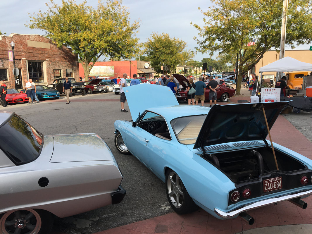
Tony Martin, Independence, Missouri - 67 Monza Coupe Project
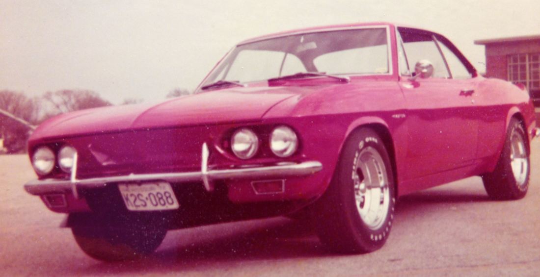
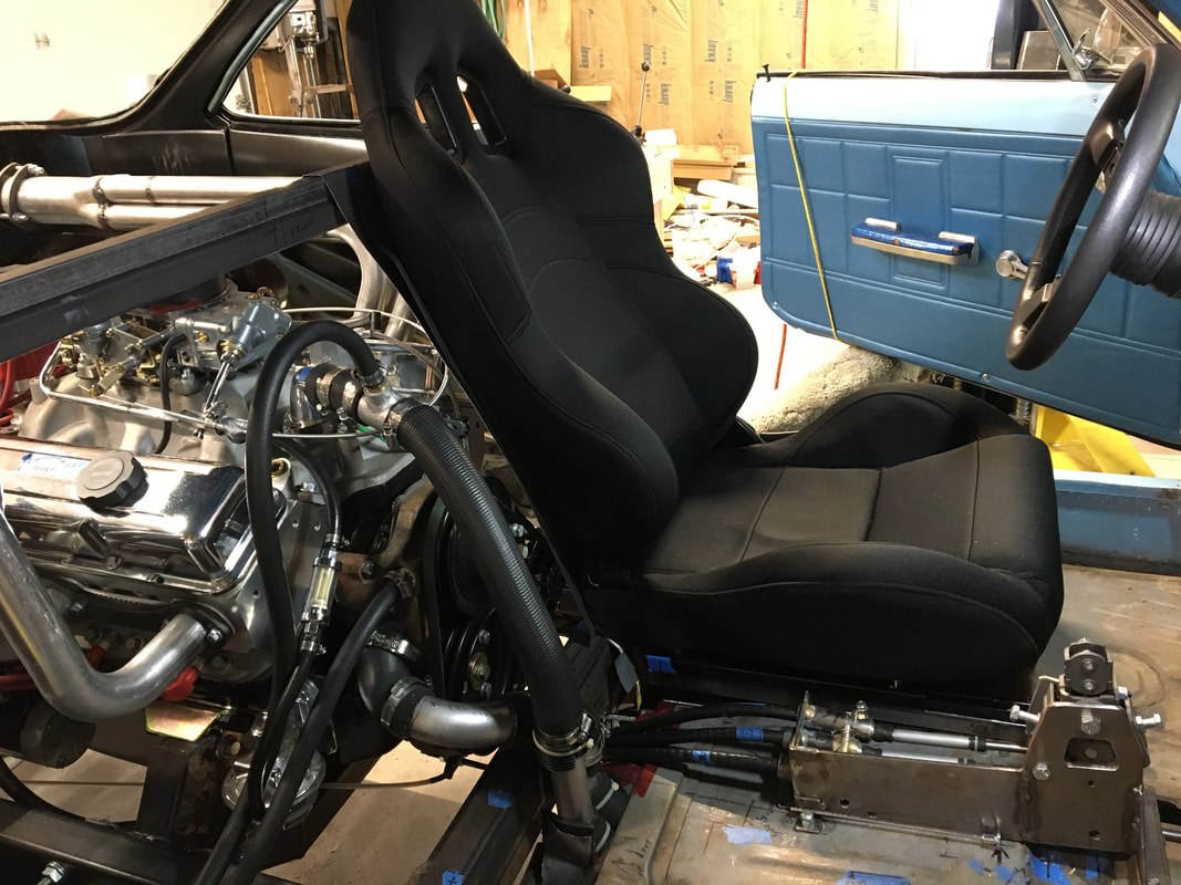
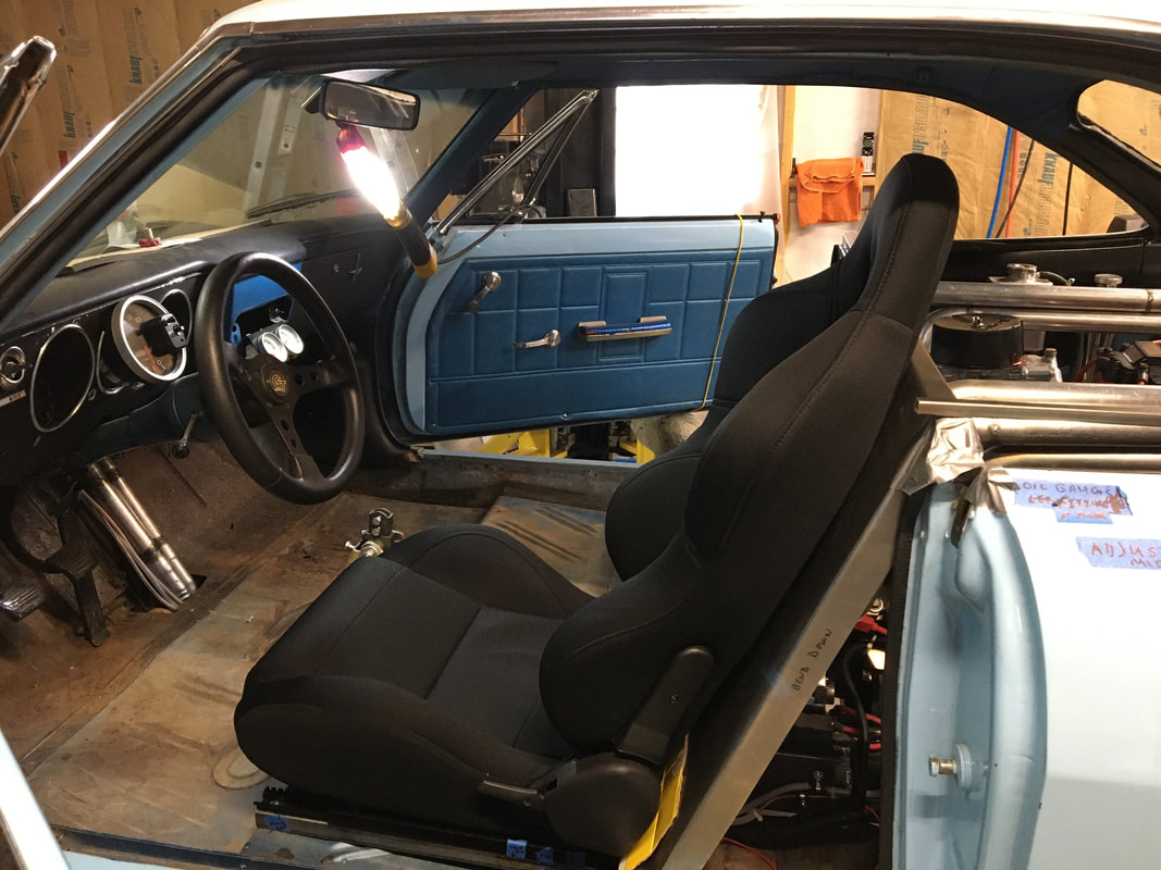
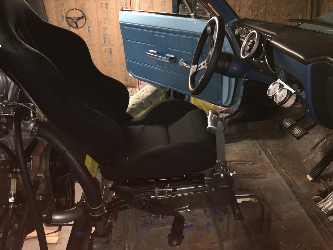
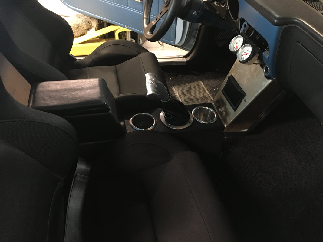
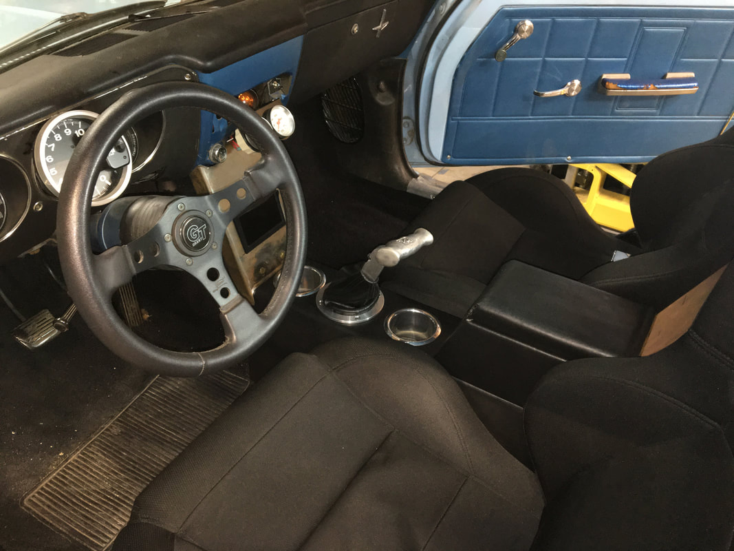
This is a 1965 Corvair Corsa Turbo 180 and was built in 1969 - 71. Bought the car for $650 & sold the turbo motor for $250 (in 1969). I originally planned to use the Crown conversion but was unaware of the requirement to use the 66 & later transmission when I bought the car. After a lengthy search for a suitable transmission that fit the budget of a high school kid, I went with a 68 Chevy truck 3 speed. I removed the tail shaft housing, designed & machined an adapter plate (2 pieces required – machined in my high school shop after class) to mount to the 3:55 posi diff, & had a local machine shop shorten & re-spline the output shaft to fit into the pinion shaft. The Chevy 3 speed appeared to be maybe 2-3” shorter than the standard Crown setup, so this one has plenty of leg room & still has adjustable seats. Seats are from a 66 Galaxie 500XL, with the springs removed from the back & replaced with foam to provide significantly more side support.
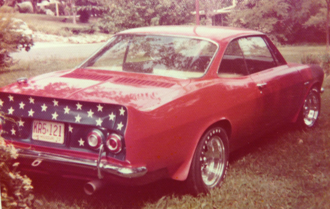
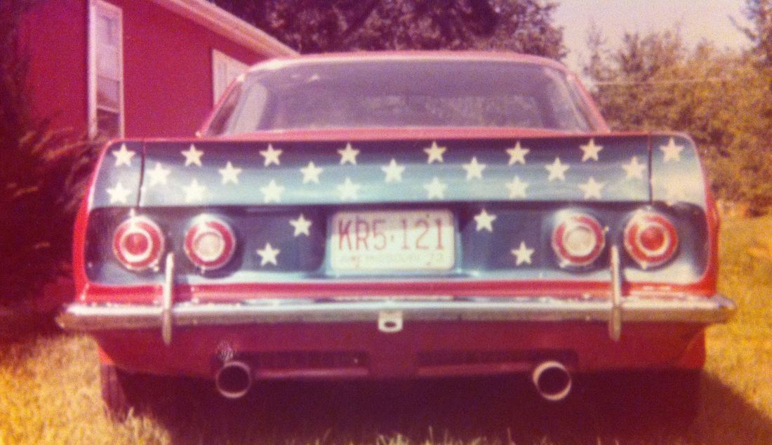
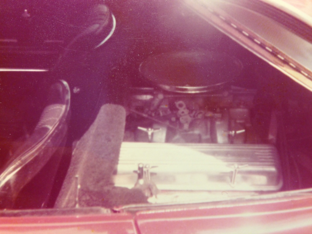
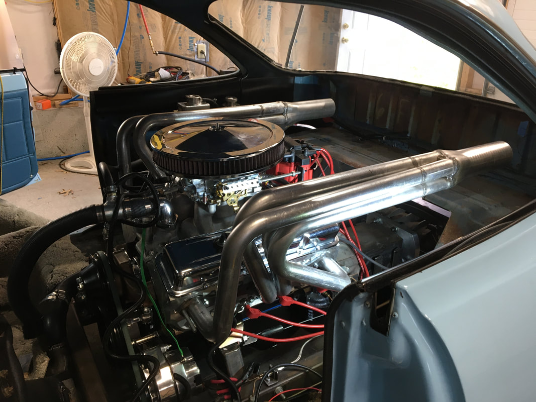
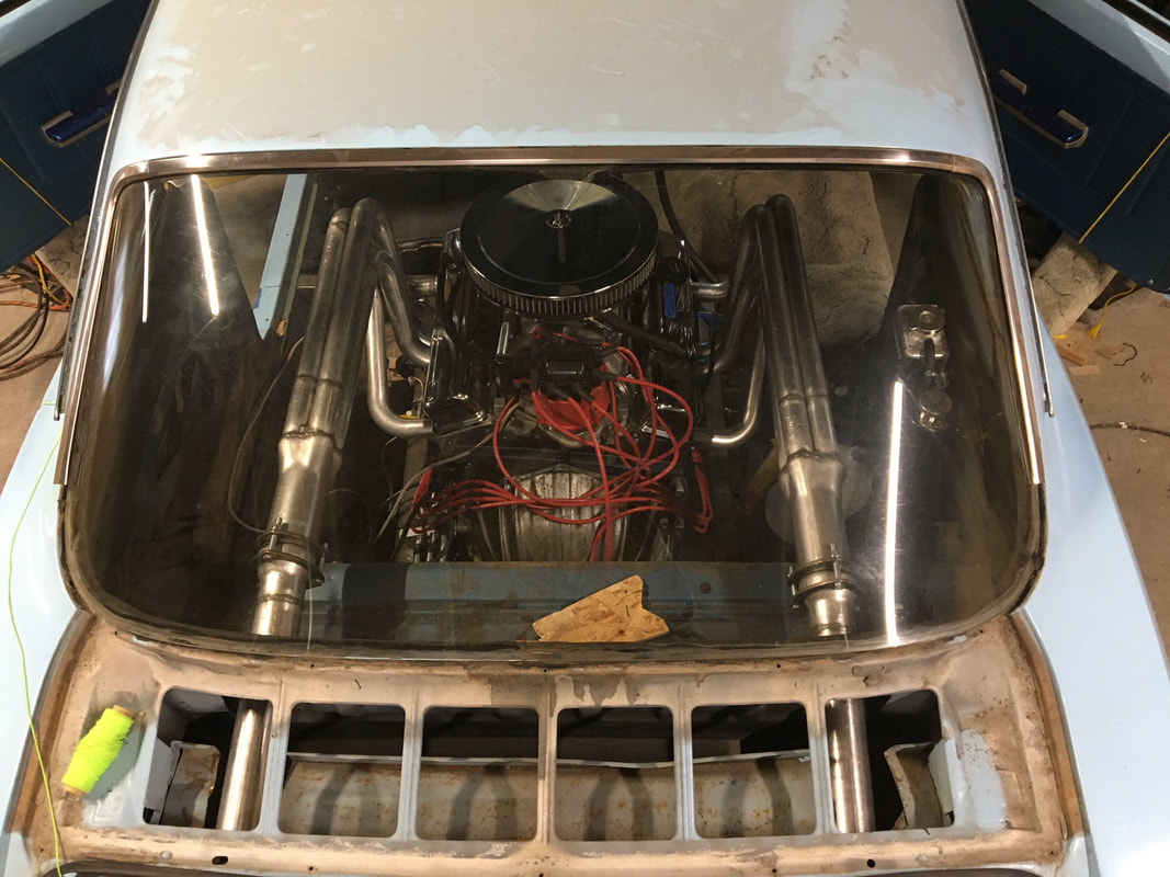
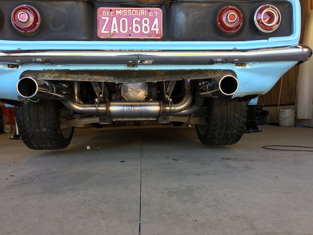
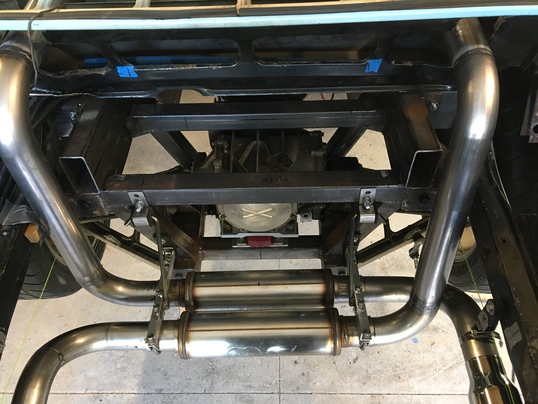
The engine is a 327 bored 60 over with a 097 Duntov solid lifter cam, double hump heads, Holley 4 barrel, & Edelbrock intake. Estimated power was around 360hp. The custom headers feed directly into Hooker Header Mufflers, which end up at the rear valance panel. The exhaust tips are 4” drive shaft tube.
The fender flares, front & rear spoilers are all hand formed steel. The stars on the back are 3M reflective tape applied over deep blue metal flake and under a clear coat.
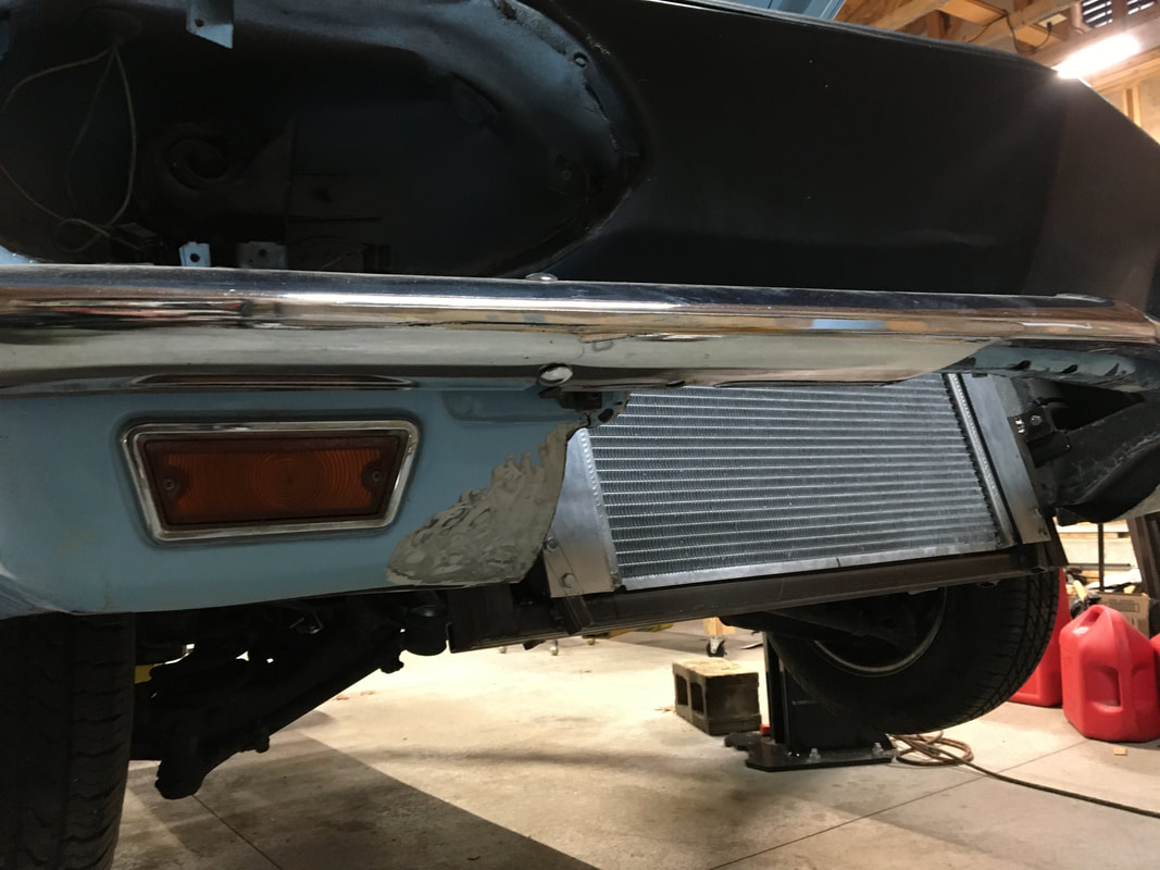
I tried all sorts of combinations to try to make a radiator work in the back. I finally gave up & put it in the front where it belonged. I removed the original gas tank and put a Mustang tank in the back. It just needed to be cut in two & narrowed about 3 inches to set on the frame rails as the floor of the rear trunk just like in the Mustang. The gas cap on the right rear quarter is from a TR3 or TR4.
Sorry about the low quality pictures (there were no digital cameras back when these pictures were taken).
I sold this car back in 1984 (Kansas City, MO area), & about 5 years ago, I started looking for it again. After a couple of years of looking, I was finally able to find it, however it was way too far gone for me to want to buy it back, having spent at least 15-20 years broken (spider gears) & stored outdoors to rot away infested with all sorts of wild life. From what I gathered from the guy who now owns it, he plans to keep the “rat rod” look. I’m looking forward to seeing it back on the street again.
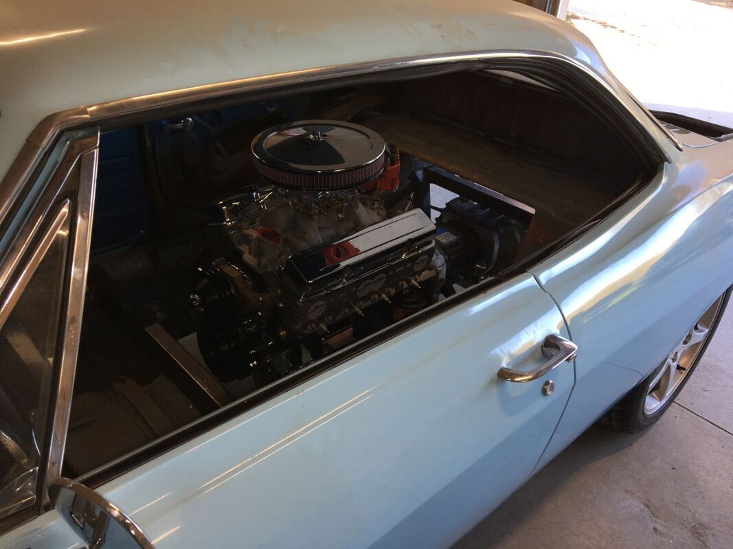
Last week I bought another Corvair – this time a 67 Monza coupe. My plan is to build this “new” one to look just like my previous one. Although this time I plan on using the C5/big car Saginaw combo.
Stay tuned
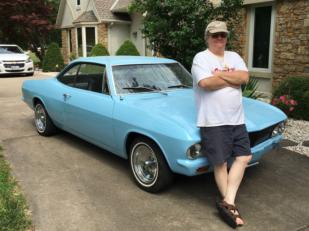
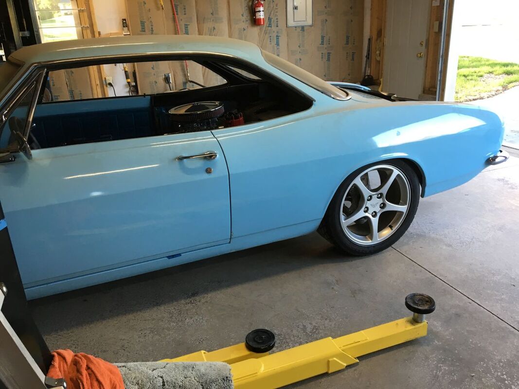
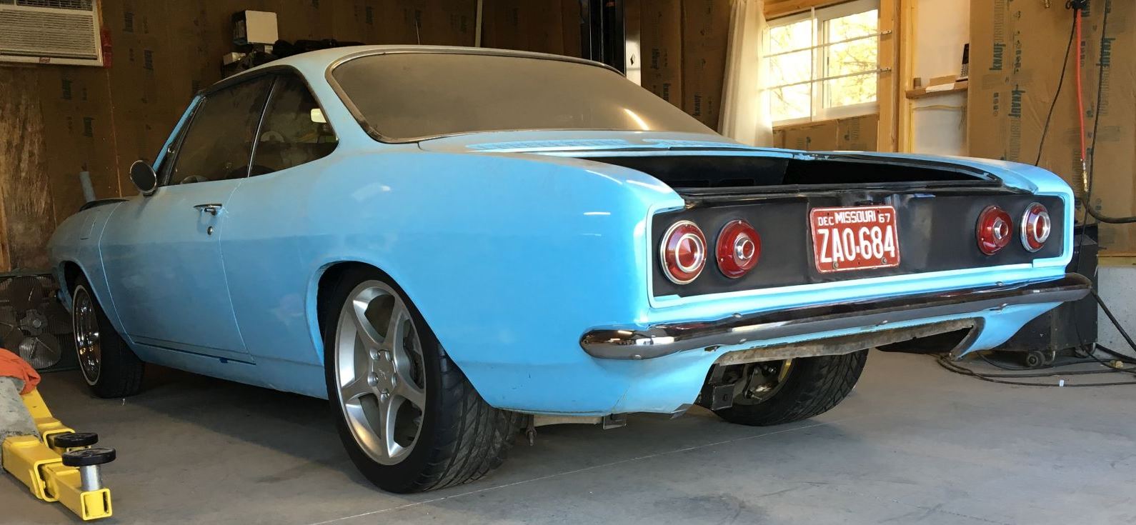
Here's the "new" 67 Monza - waiting for the new garage construction to be completed - before starting the transformation into a real life "water pumper"
May, 2018 - Tony's Work Begins...
Here's my progress to date for my latest build. May 2018
Although I bought the “new” 67 Monza about a year ago, first I had to build a garage for it & then I had to buy & install the car lift. In the meantime, I’ve been working on my BC Sag/C5 Diff adapter plate. It’s almost done. A couple of details yet to figure out & finish, & then I can actually start on the car.
I’ve been able to see some pictures of a couple of adapter plates made by others and I’ve had some discussions with a couple of the builders. I decided to use some of their features and also use a couple of my own.
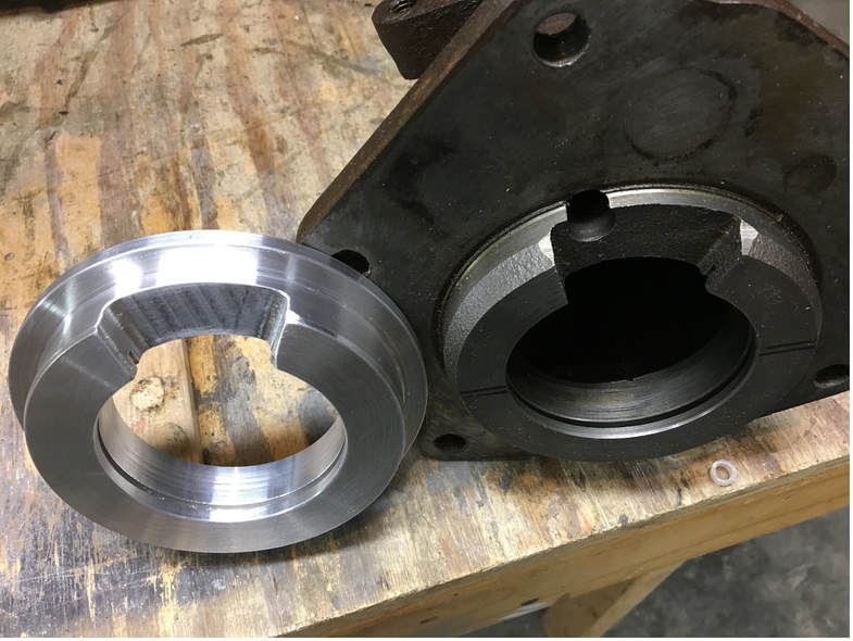
I decided to make a transmission bearing retainer out of aluminum & recess it into the 1" thick 6061 aluminum adapter plate. It has a snap-ring groove as well as an oil hole drilled for oil flow just like the original tail shaft housing.
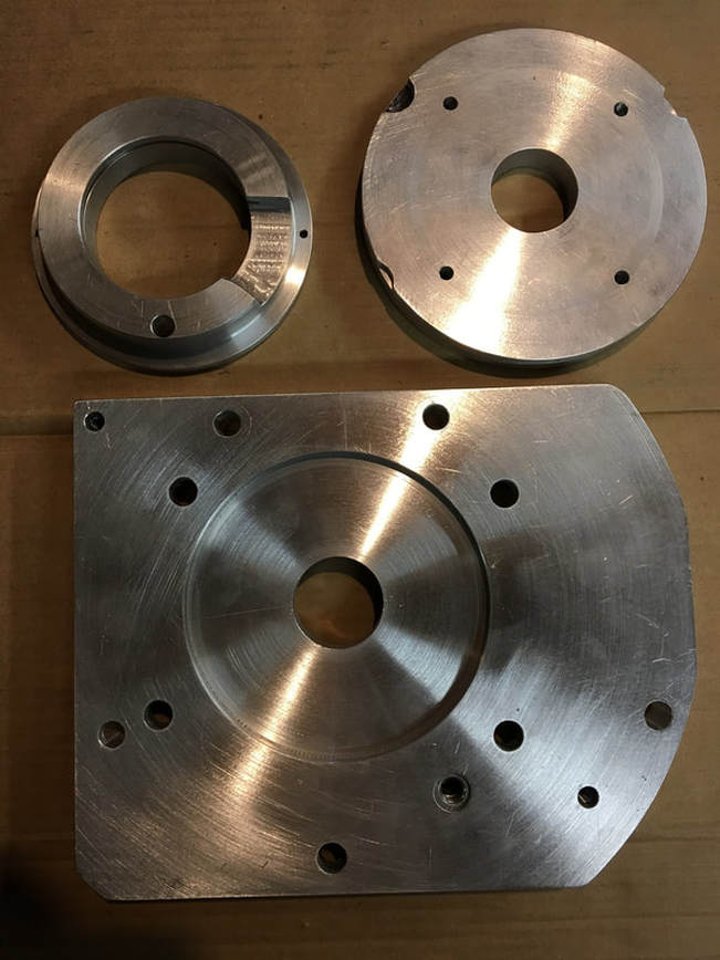
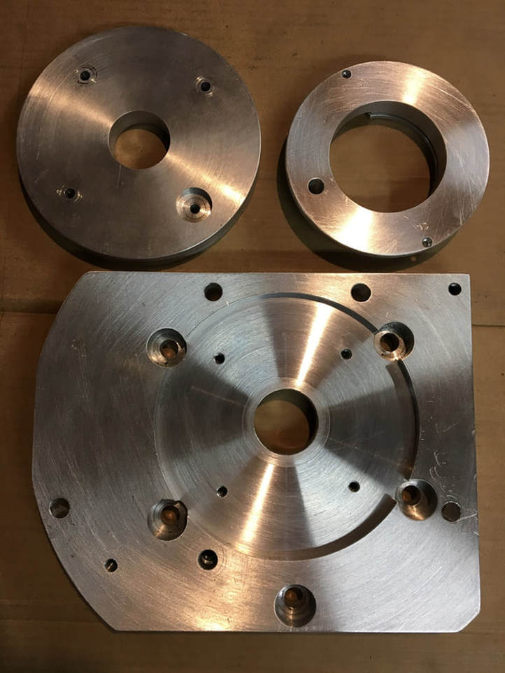
These are the 3 pieces to the adapter plate, as shown from the transmission side.
Top left is the bearing retainer, top right is the diff locating plate. Note that some amount of machining is required in the trans side of the
diff locating plate for 3 of the transmission bolt heads. The bottom is the 1” adapter plate, showing the recess for the bearing
retainer. The weird overall shape is because I used a lathe (12” max diameter) instead of my mill to make sure all the machined features on each side are concentric.
The same 3 pieces as shown from the differential side.
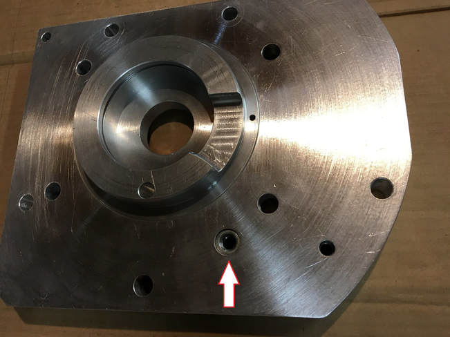
The bearing retainer set into its recess in the adapter plate. Note that it is already positioned with the gap where it needs to be to remove the snap ring. The arrow is pointing to a steel threaded insert. This is about the only way to make a bolt work at the bottom of the differential.
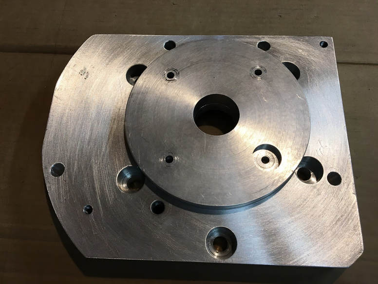
The differential locating plate set into its recess in the adapter.
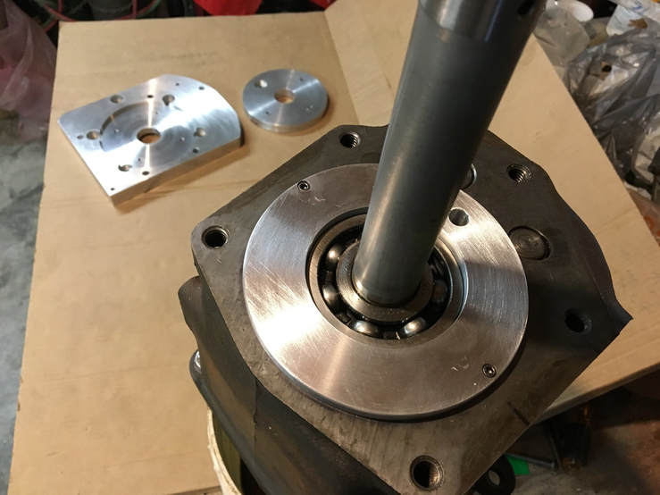
The bearing retainer mounted in place in the transmission. Note that it
is screwed to the transmission face. This allows the bearing retainer & its snap ring to stay in place when the differential & adapter plate is removed. It is also already positioned with the gap where it needs to be to remove the snap ring.
is screwed to the transmission face. This allows the bearing retainer & its snap ring to stay in place when the differential & adapter plate is removed. It is also already positioned with the gap where it needs to be to remove the snap ring.
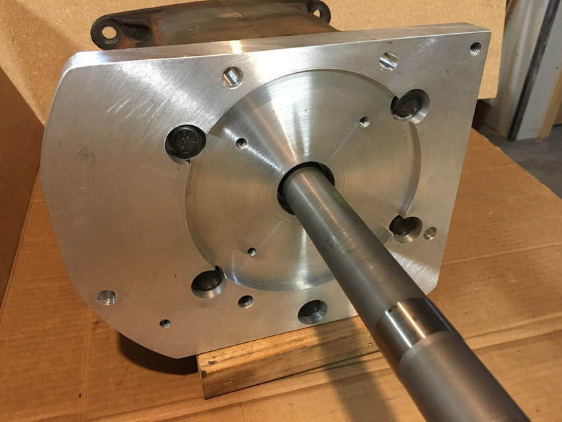
The adapter plate bolted to the trans. Note the recessed holes for the
bolt heads.
bolt heads.
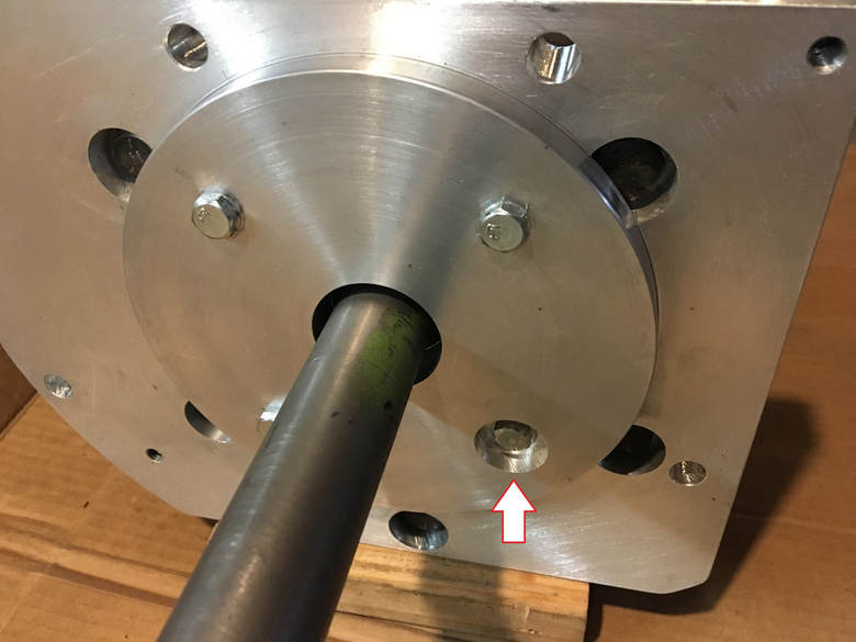
The diff locating plate bolted to the adapter plate.
(I haven’t cut the groove for the oil ring seal just yet.)
The bolt with the arrow needs to be recessed to avoid contact with the
ring gear.
(I haven’t cut the groove for the oil ring seal just yet.)
The bolt with the arrow needs to be recessed to avoid contact with the
ring gear.
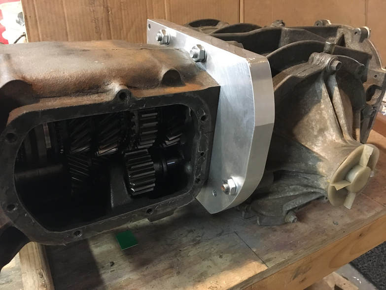
The extra holes in the adapter plate were used to hold the plate to my lathe faceplate for machining.
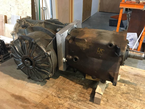
My home made faceplate which also has a 1.5” diameter stub to very precisely fit into the center holes in the adapter plate & the locating plate. This ensures several things; parallel front & back surfaces, concentric features (the machined recesses), and repeated mounting and dismounting of pieces without having to use a dial indicator each time.
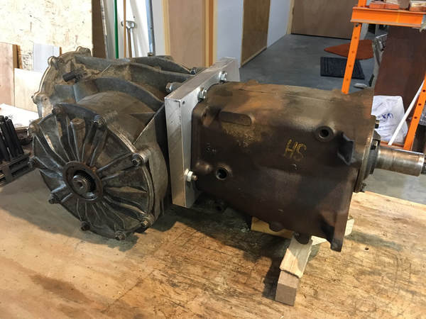
The lower diff bolt shown in this picture is critical to understand. Originally the stud used in this position is what your local hardware store calls a carburetor stud. It has a short length of threads on one end, some amount of non-threaded space, and then some more threads. Since I couldn’t find one of a suitable length, I had to make my own. It’s very important to make sure the short threaded end is not too long, since the stud would screw in far enough to hit some bolts on the outside of the posi carrier. You could also use a bolt here, If you were careful. (AND made sure you used the same bolt and washers each time.)
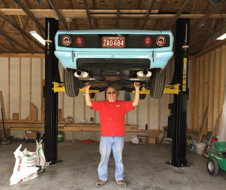
New garage and lift complete, and the car in its new home!
On my build, I still have concerns about the oil levels of the diff & transmission when allowed to mix freely. I found that the oil level for the trans is about 1 3/8” higher than for the diff. If you filled to the recommended trans level and if the oil is allowed to flow freely between the two, the actual level in the differential would be too high. I don’t know if this would be a problem or not. I've heard a couple of people mention something about using an oil seal between the trans & diff, but there is no smooth place on the main shaft to run the seal. On my trans mainshaft, there is a smooth space only about 3/16" long just past the main bearing snap ring. (see picture 6) However I don't think that this space is big enough to be practical for an oil seal.
After discussions with some other builders on the issues created by the differences in oil level between the transmission & the diff, I replaced the Saginaw rear main bearing with an equivalent part number that has a built in oil seal. This keeps the oil in the transmission from migrating to the diff. I also added an additional hole just above the bearing retainer so both the trans & the diff would share the vent already in the diff.
After discussions with some other builders on the issues created by the differences in oil level between the transmission & the diff, I replaced the Saginaw rear main bearing with an equivalent part number that has a built in oil seal. This keeps the oil in the transmission from migrating to the diff. I also added an additional hole just above the bearing retainer so both the trans & the diff would share the vent already in the diff.
January, 2019 Update
|
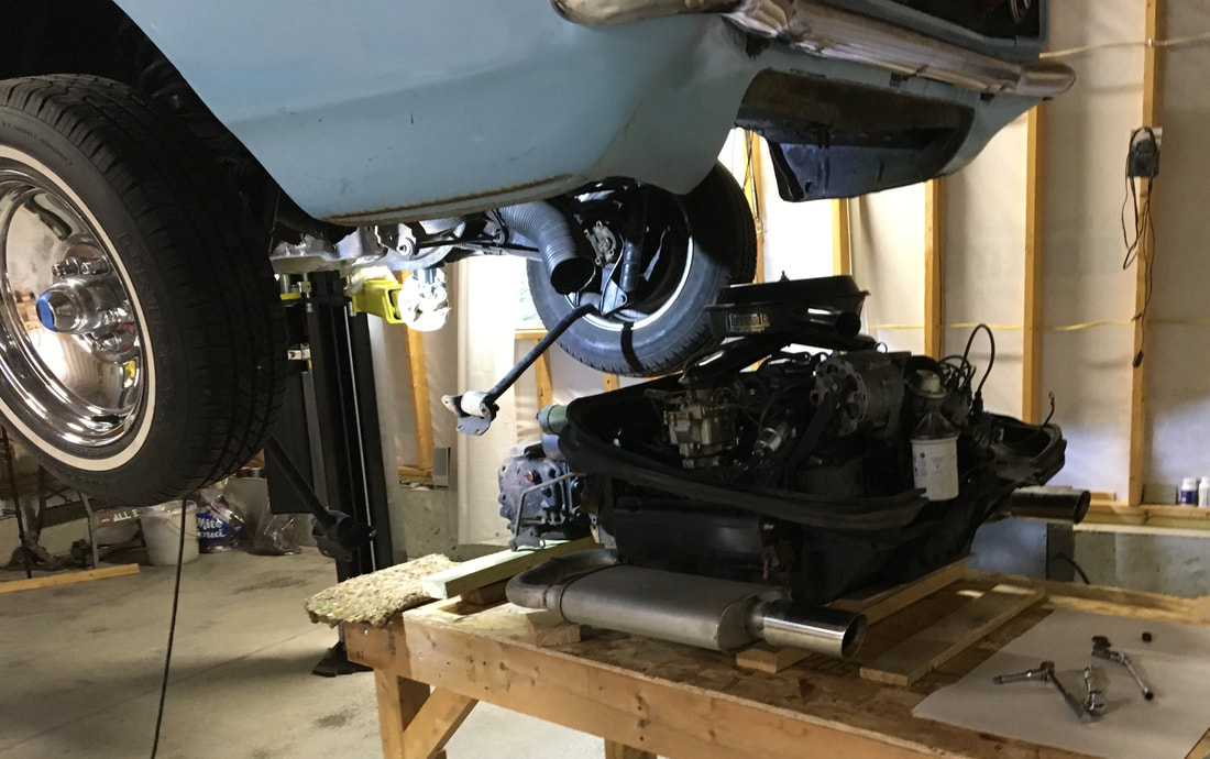
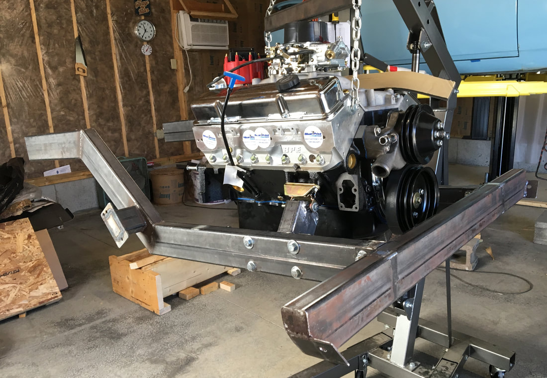
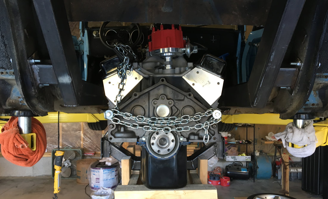
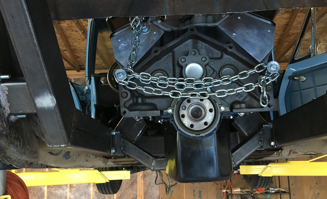
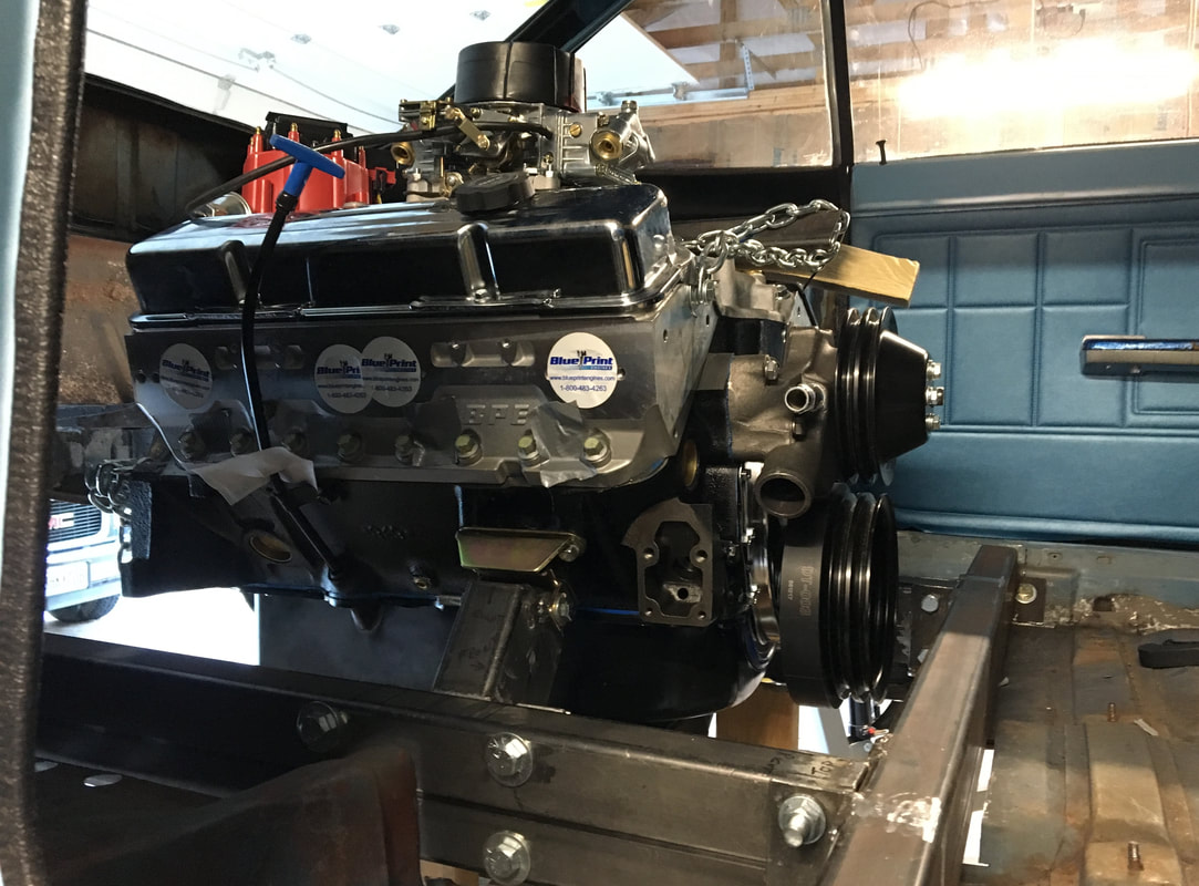
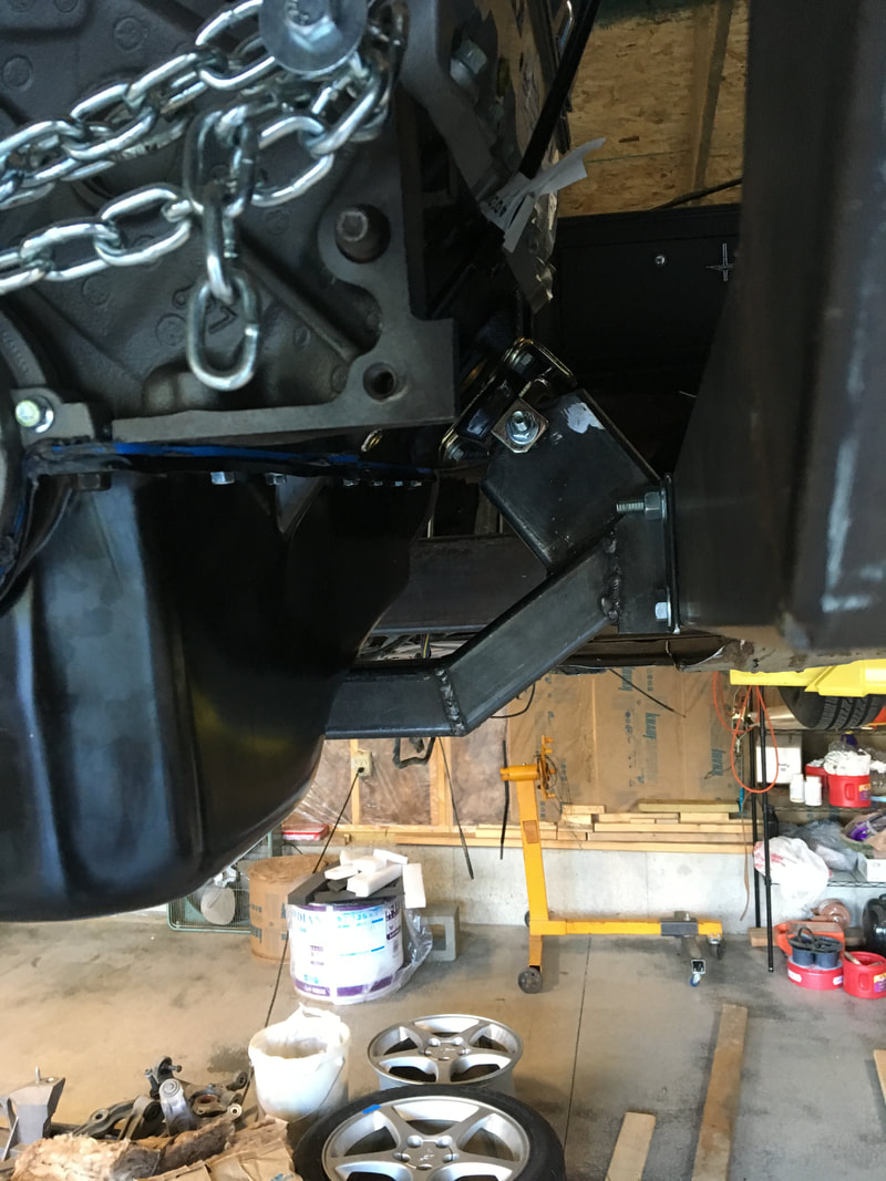
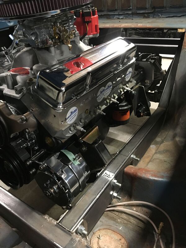
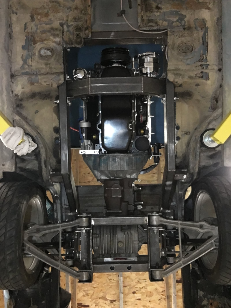
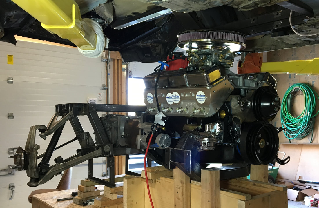
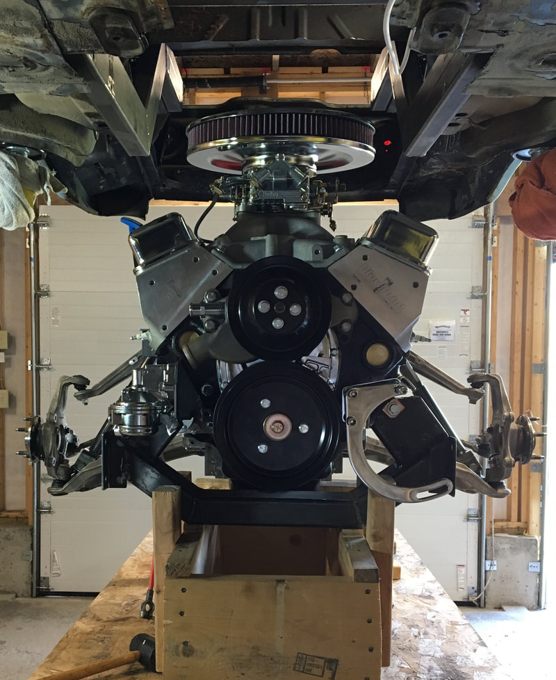
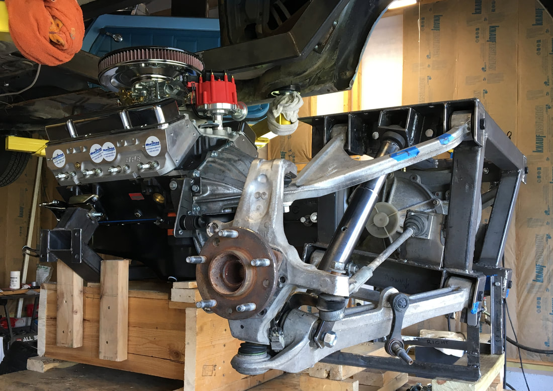
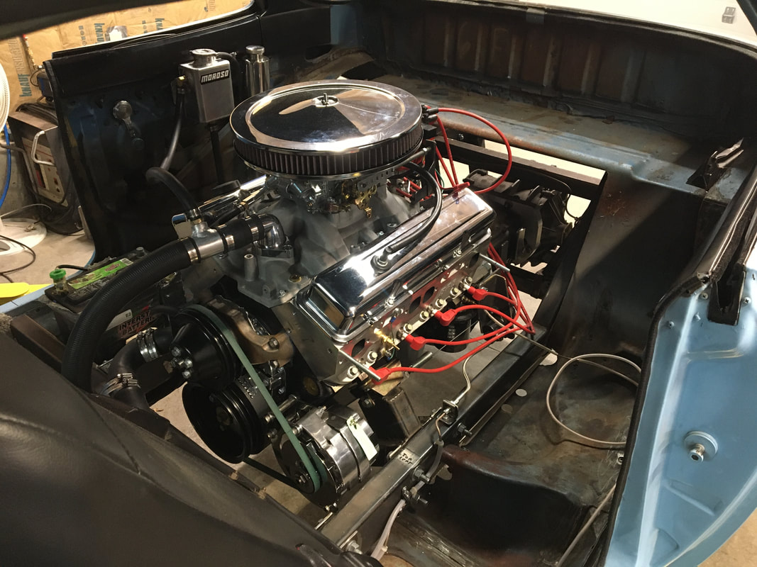
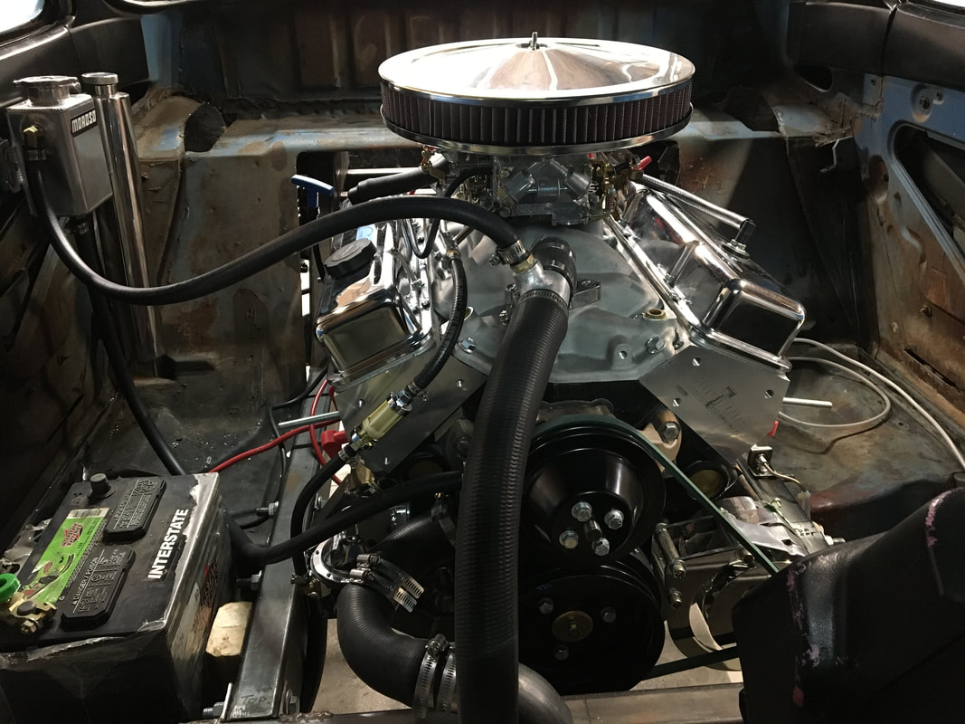
New engine in place
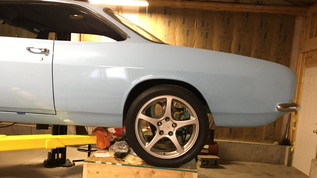
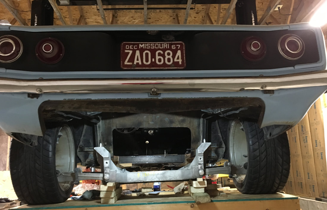
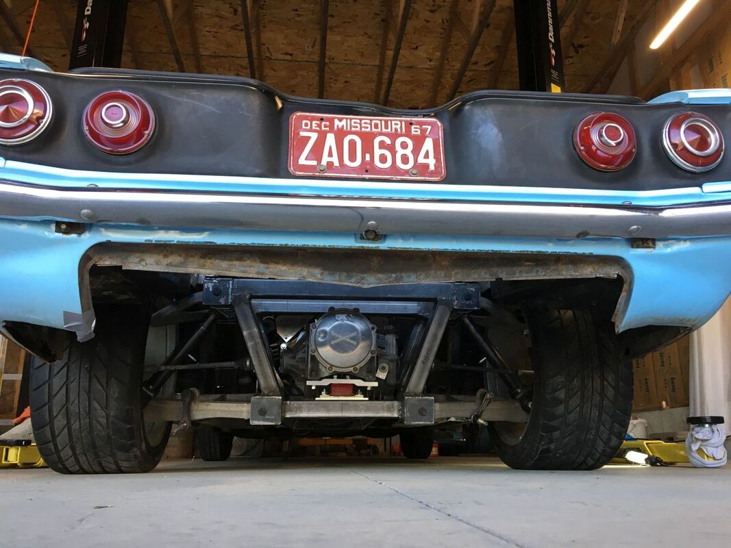
Trial fit of stock C5 Corvette rear suspension, wheels & tires.
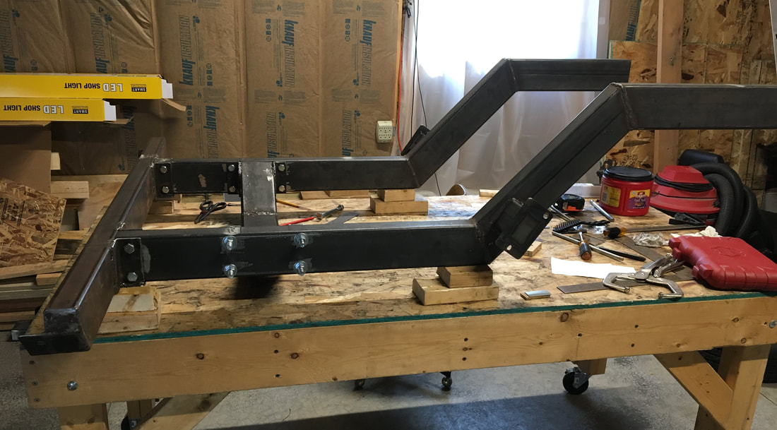
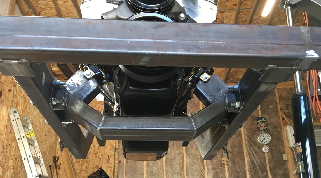
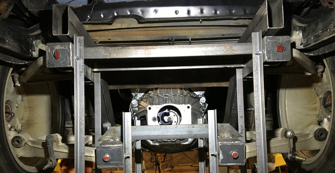
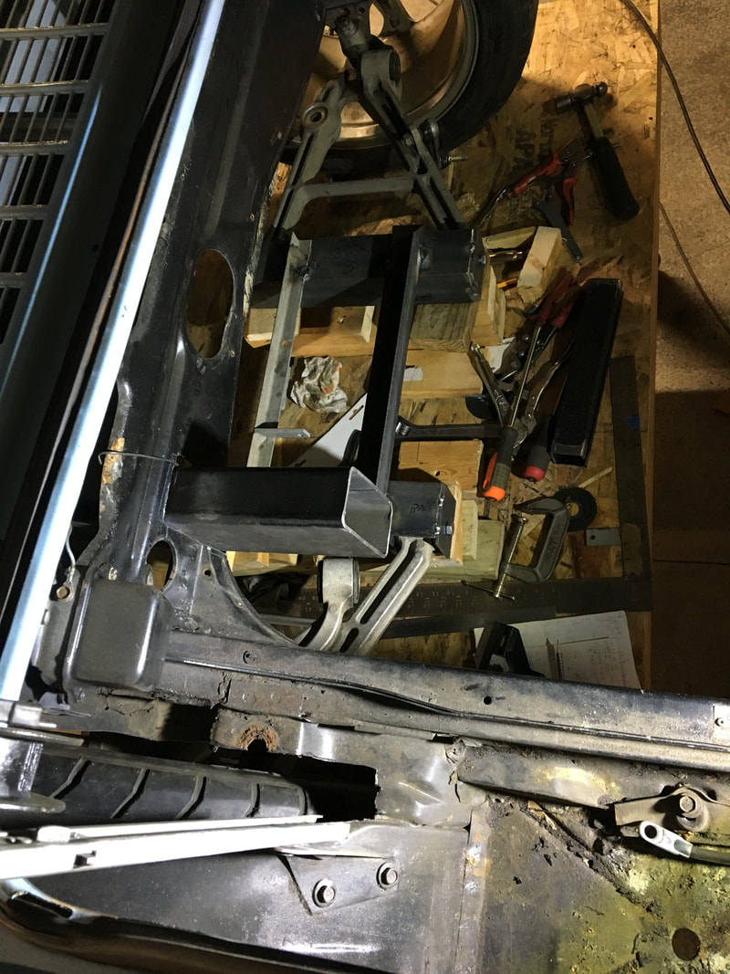
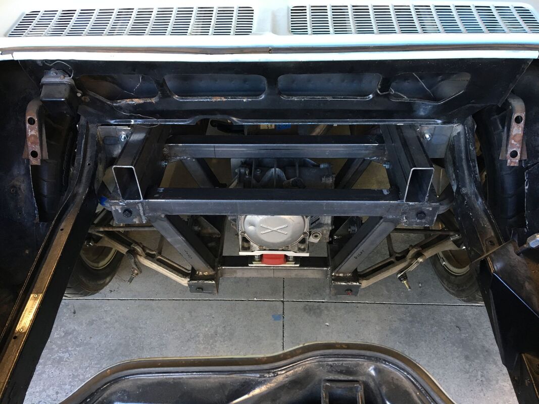
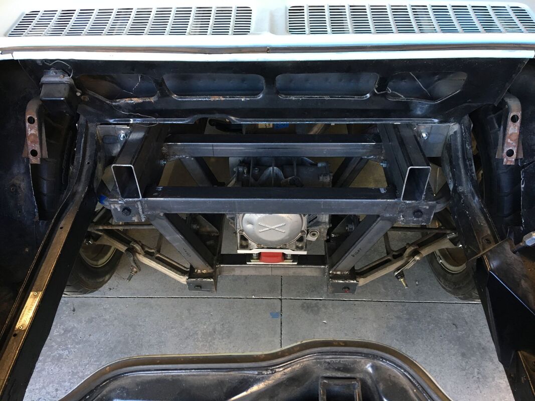
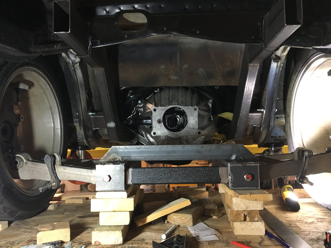
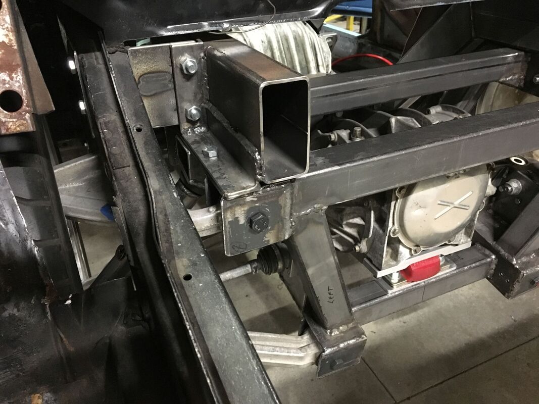
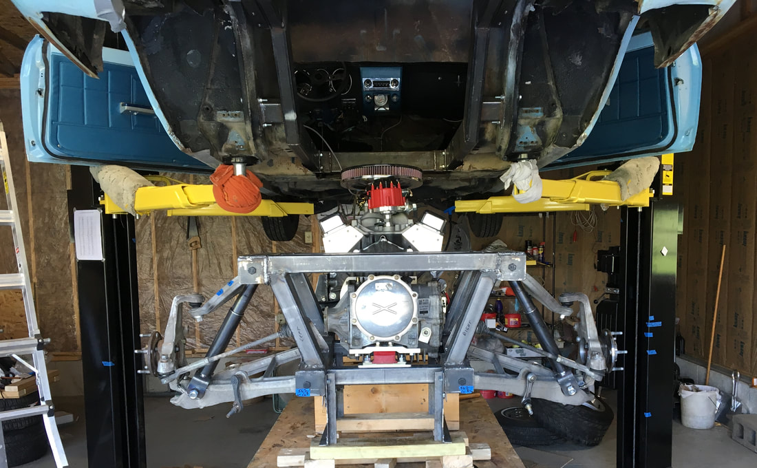
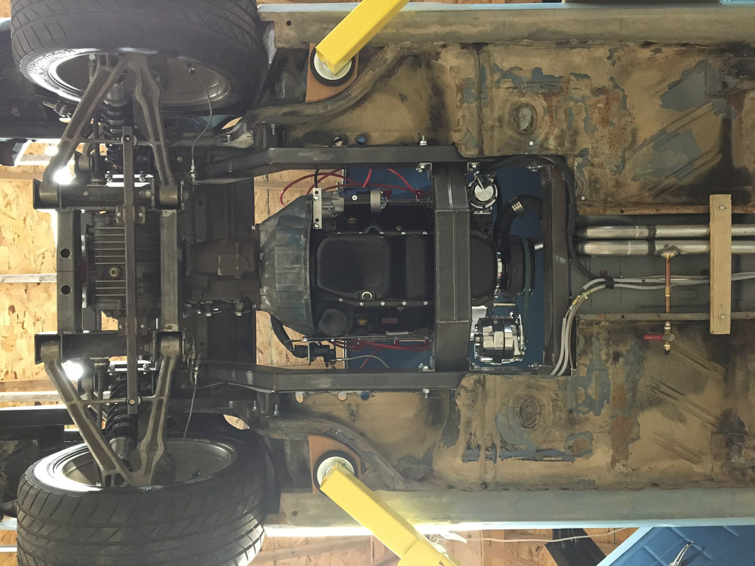
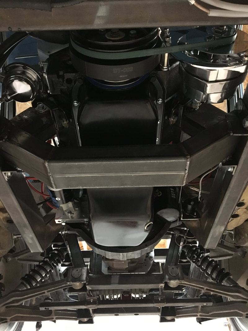
I decided to make the suspension framework out of steel instead of using a narrowed C5 cast aluminum cradle. I did buy one, but I only used it for dimensions. (I still have it if someone wants it.) I’m using 3” steel angle 3/16” thick. One set for the lower A arms & another for the uppers.
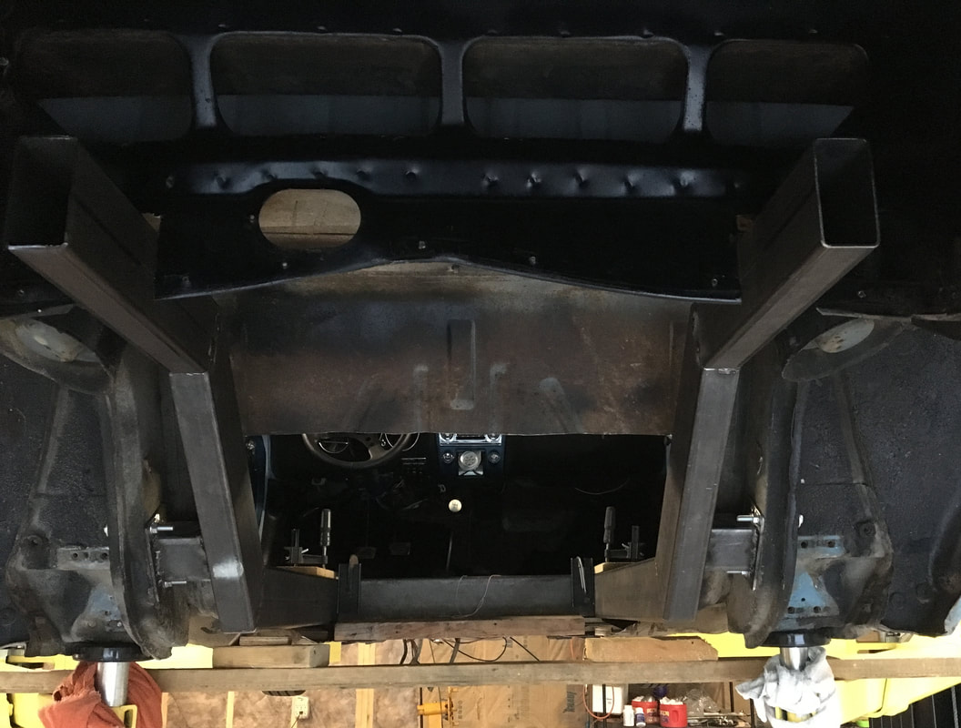
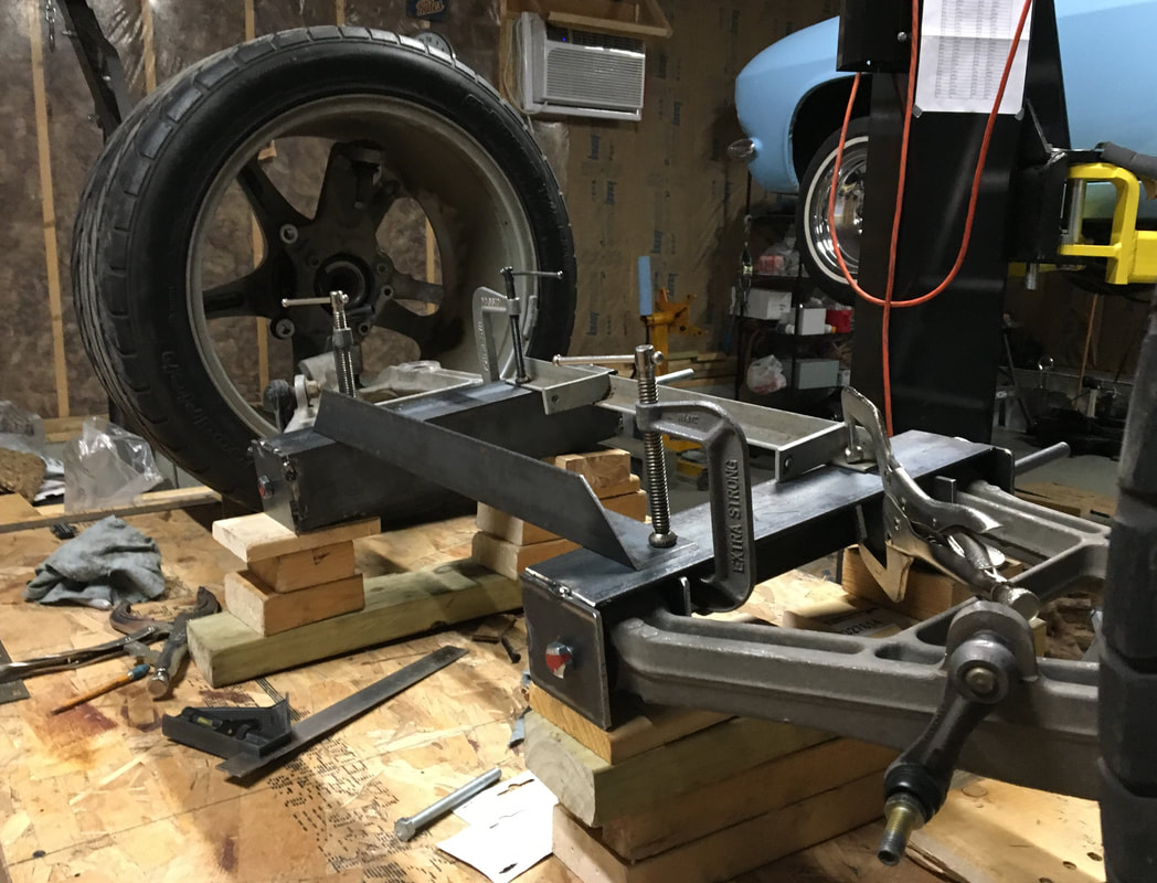
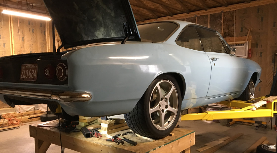
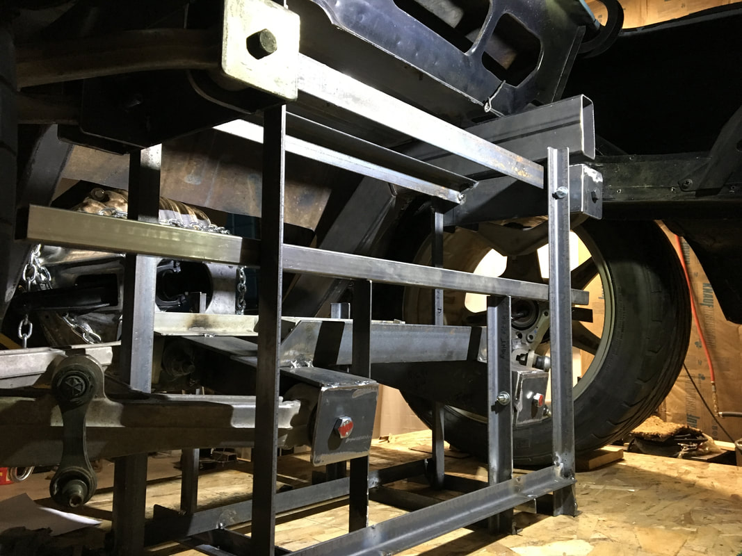
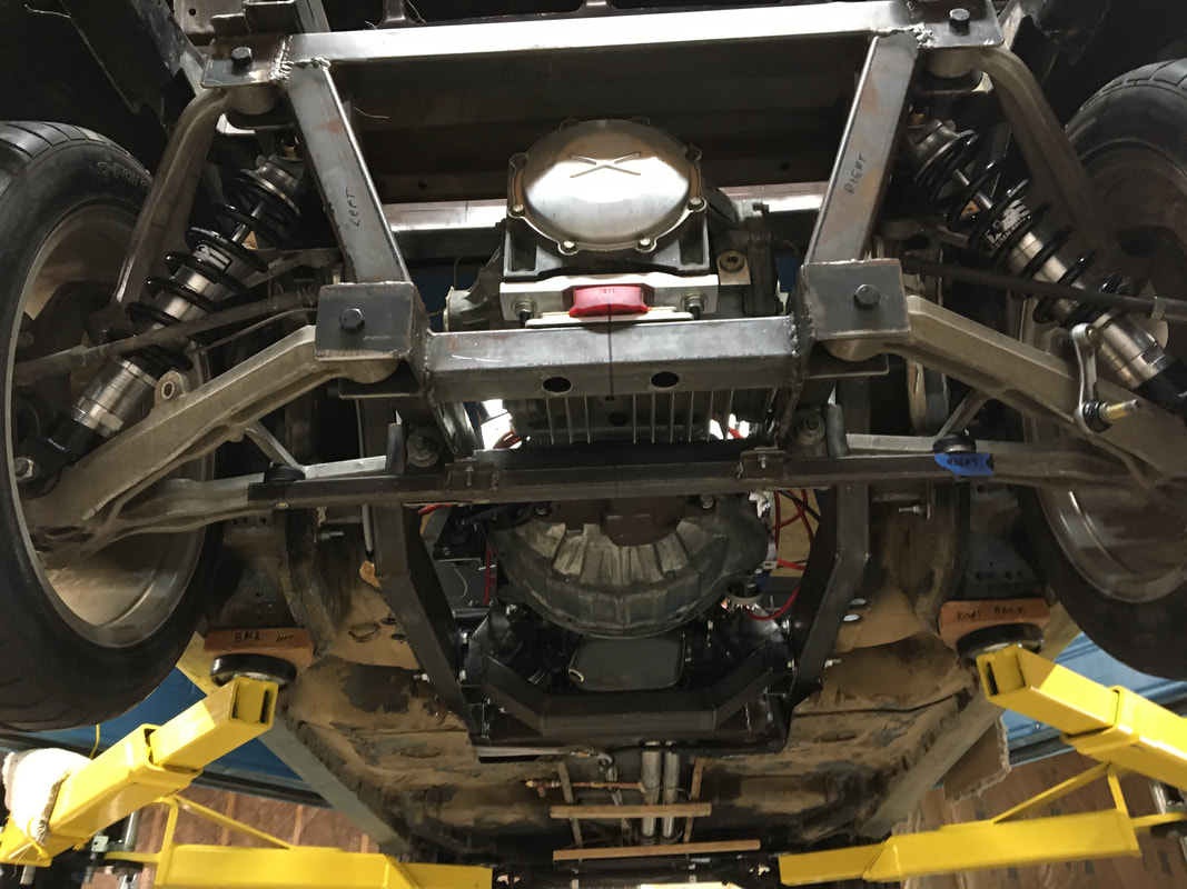
Complete cradle jig set up under the car with A arms, spindles, wheels & tires to check fitment. After this step, I was able to verify that going with a 7” narrowed track would indeed work with the stock C5 tires & wheels. Note how the top of my steel cradle is positioned relative to the subframe. The complete rear suspension will be bolted to the subframe “kind of similar” to the Dobbertin setup.
There will be 2 2” square tube cross pieces between each angle iron cradle half. The rear cross tube will hold the mount for the diff. There will also be additional 2” tubes at each corner from the lower cradle pieces up to the top set. This jig is essential to get these additional tubes properly sized & positioned. New “normal” ride height of 25” to the top of the wheel opening. Doing this kind of work and doing this kind of prototype work is SO MUCH easier on old knees when using a lift and on a table like this! (Yes, I also have a roll-around chair as well.)
|
Trial fit of stock C5 Corvette rear suspension, wheels & tires.
No worries! It’s just a simple "math problem".
I didn’t want to modify the fenders, so I decided on a 7” narrowed track width. I did a little bit of trimming in the wheel wells – only in the inside area near the Corvair frame. I did not need to modify any part of the wheel opening area. When I do get into the bodywork part of this project, I plan to do the same “mini flare” wheel opening treatment that I did on my first build. (Roll the inner lip, & remove the vertical/flat part of the wheel opening.) Using the CAD program I have, I designed & built a cradle alignment jig to get all the dimensions set up correctly in 3D - the proper slope angle of each piece, and the relative positions of each component to the others, as well as to common reference points.
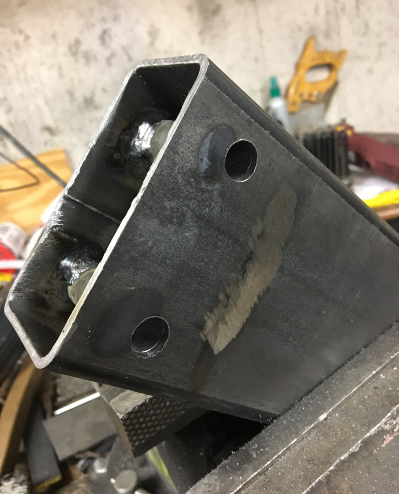
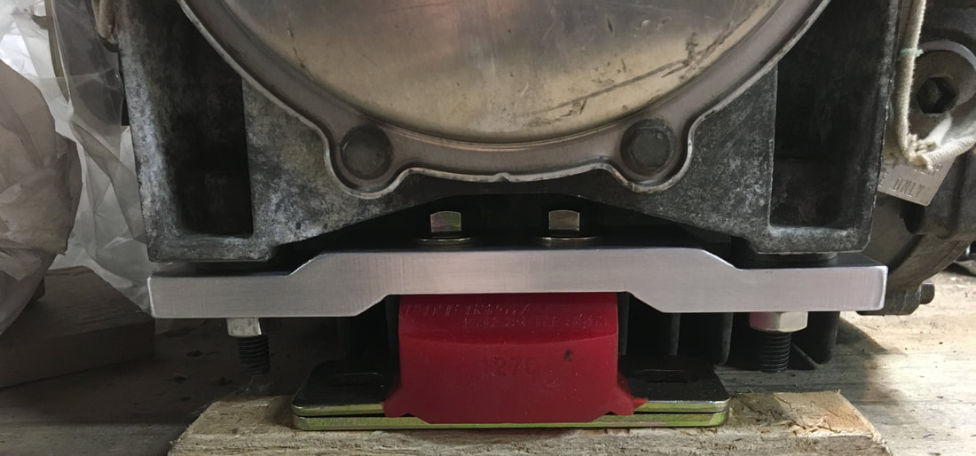
Instead of using the old stock C5 diff mount or any of the aftermarket mounts for the C5, I decided to use a lower profile polyurethane transmission mount for a Chevy from Energy Suspension (Mfr. #: 3.1158R). (It has the internal safety limits built in to prevent separation.) This mount is only 1 15/16” high. I did have to make a new aluminum mount to bolt to the diff.
|
January, 2020 Update
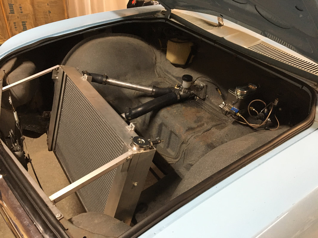
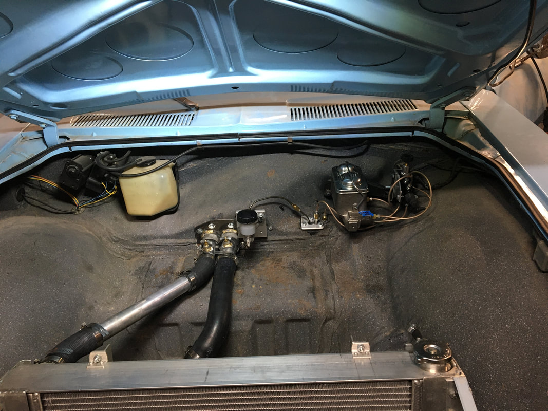
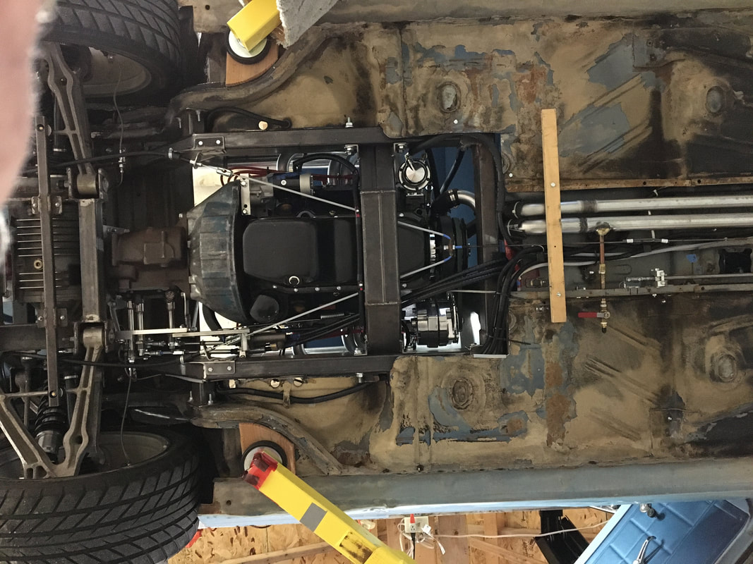
Completed rear suspension, radiator, & cooling systems. Brake lines & clutch line also completed. Now working on wiring & headers.
February, 2021 Update
|
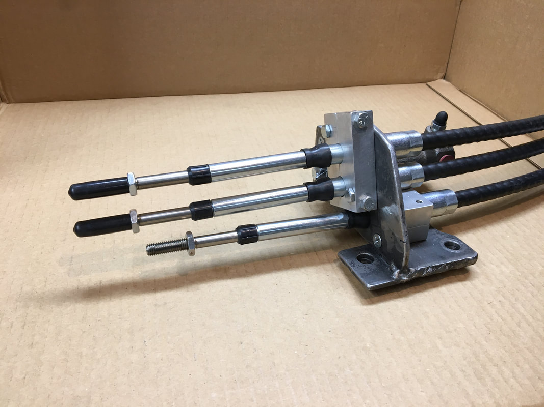
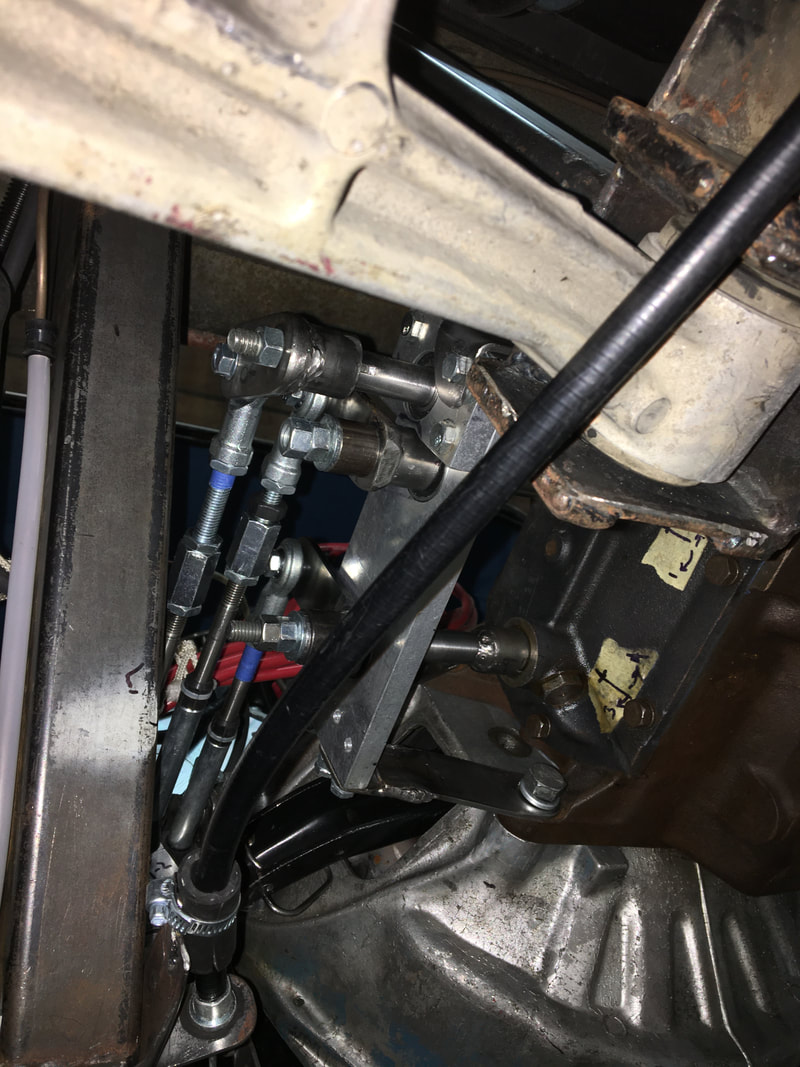
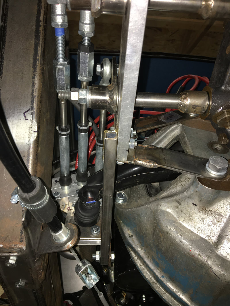
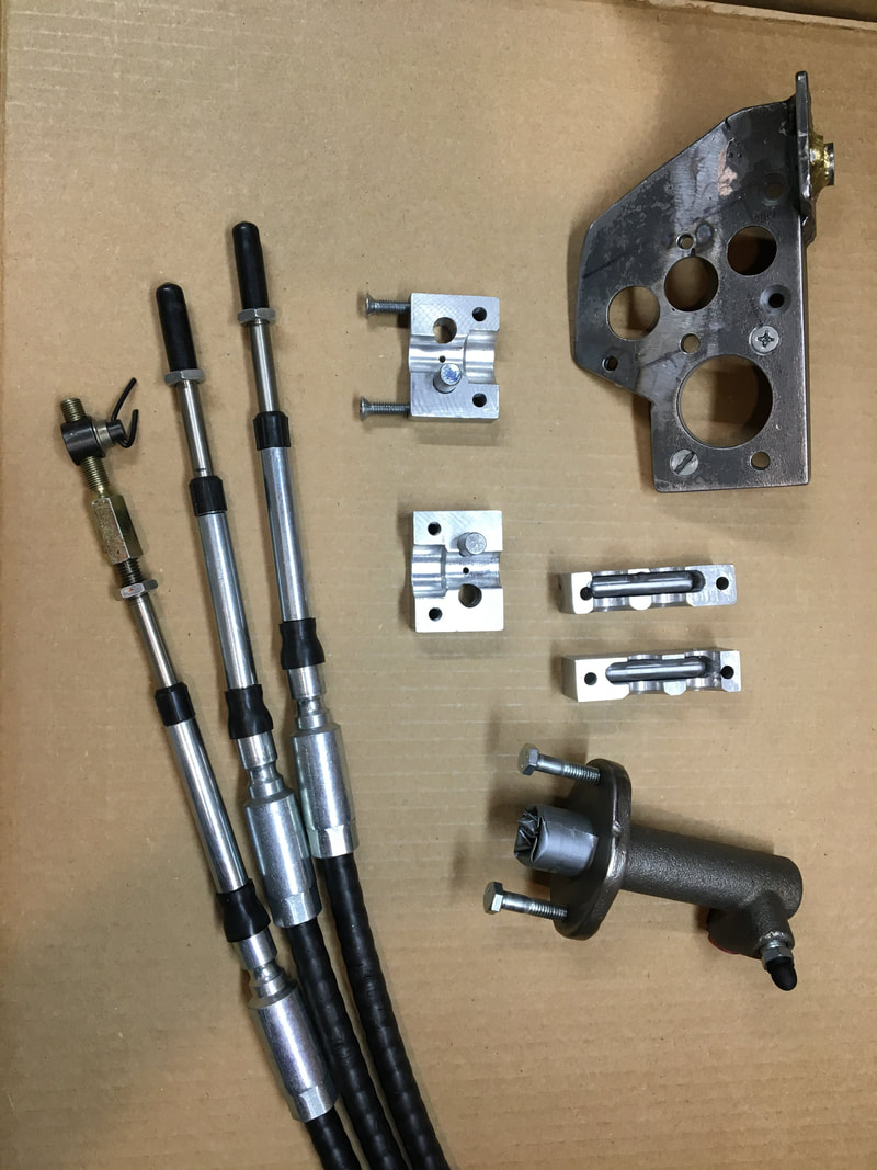
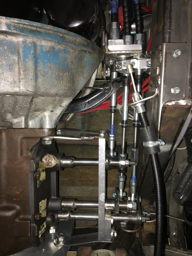
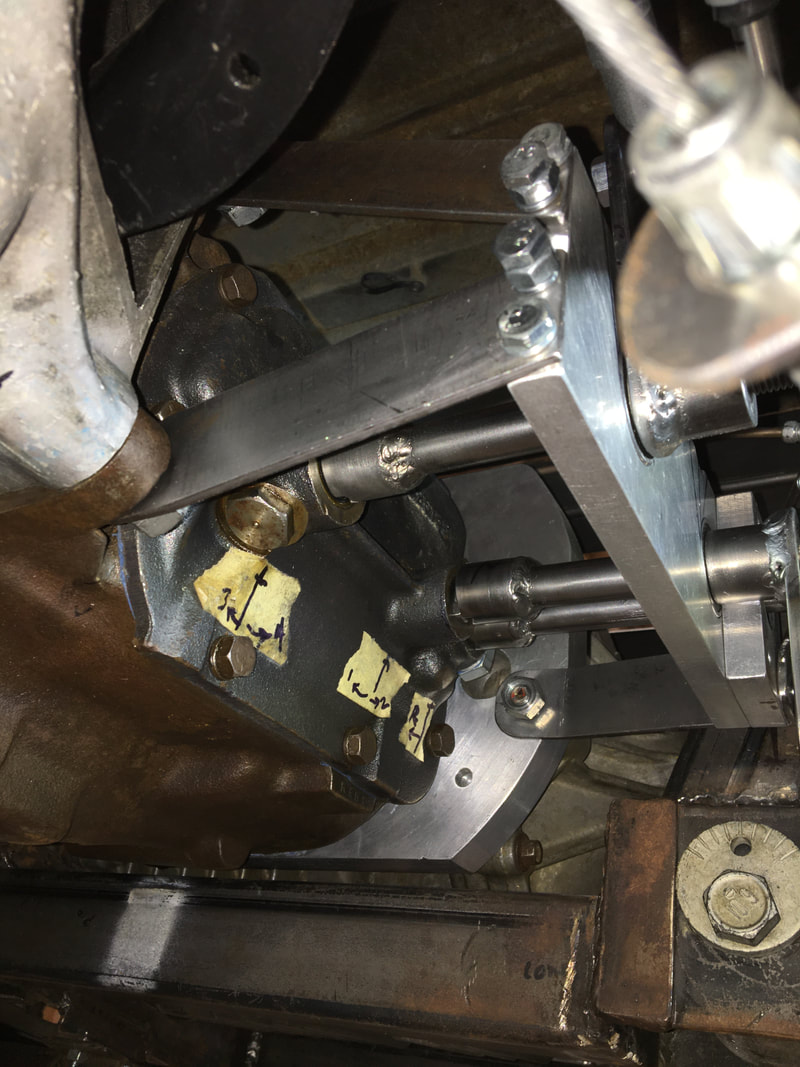
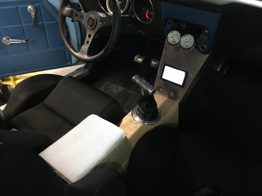
My shift linkage required many hours of CAD work, along with a bit of trial & error to make virtual to conform to reality. Everything works very well with no slack, moves freely, with no flexing.
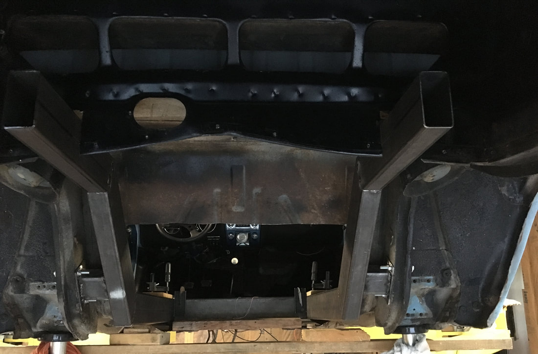
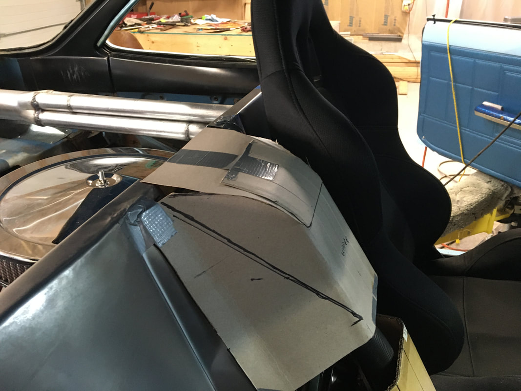
Got a good start on the firewall.
|
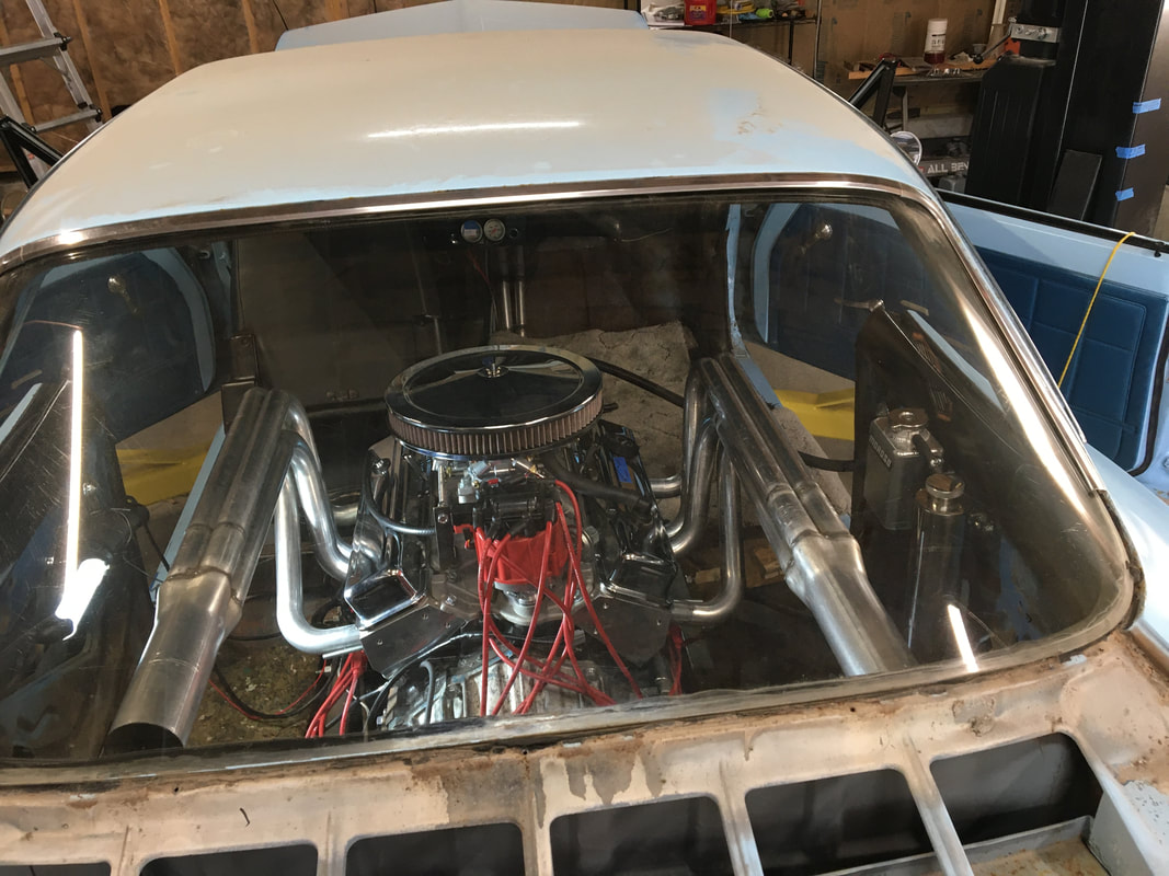
This exhaust design required a couple of hours of CAD design work.
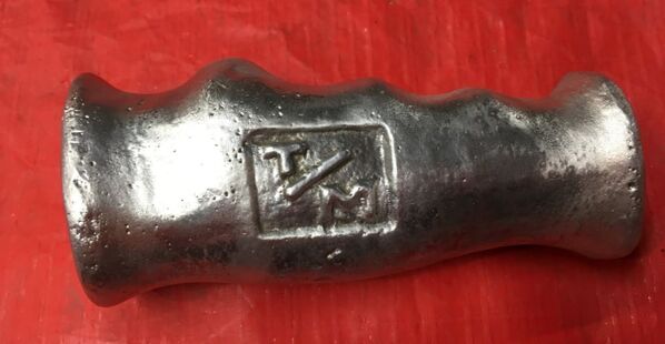
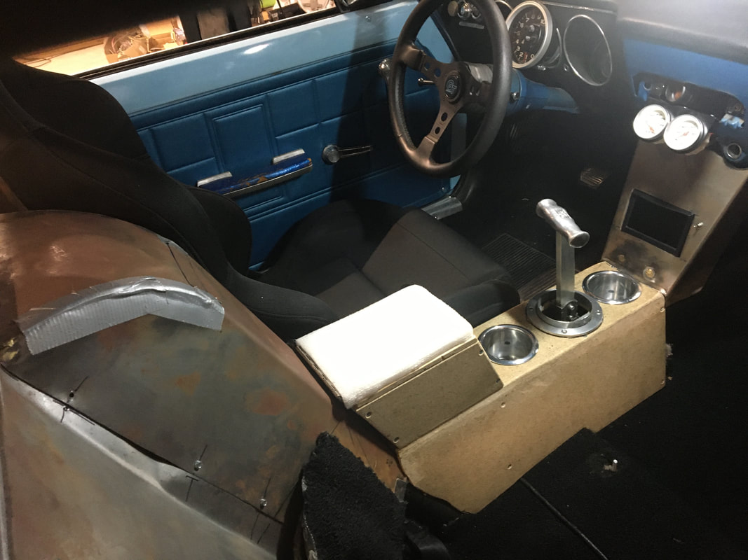
This is a cast aluminum shifter handle that I had in my original CorV8. I made this in my high school shop class. (It's the only thing I have left from the car.)
Way back in the '60s & 70s, Hurst & Mickey Thompson made various accessories with their names &/or logos. I decided to make my own logo using my initials ;) |
March, 2021 Update
It’s alive!
I’ve put 30 - 40 miles on it so far!
I had a couple of minor issues but they’ve been fixed & everything works great!
I hope to make the first local car show this Saturday.
I’ve put 30 - 40 miles on it so far!
I had a couple of minor issues but they’ve been fixed & everything works great!
I hope to make the first local car show this Saturday.
December, 2021 Update
I took a break from the car project to build a Christmas tree for the front yard. It's 12ft tall & 8ft wide at the base. There's an Arduino micro computer & 8 channel relay board in the Tupperware box near the base. The tree has 8 separate light strings which are sequentially turned on & then off. A strobe light is mounted on top.
