Robert Depalo - Hot Springs, Arkansas
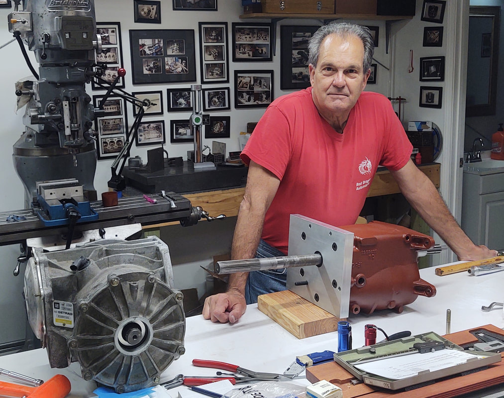
Mark Allen commissioned Bob Depalo to build a unique Corvair Conversion for both track and street use. This request caused Bob to make some chassis changes because the build started as a track car only. Bob has experience with building Corvairs and race prepared Maserati's. His skills as a machinists and electronics expert just enhances the build.
Bob started this project by first making a week long trip to visit other members with unique Corvair Conversions and/or fabrication skills to view the approaches used by a number of the V-8 Registry members to complete their builds. His journey included visits with Phil West, Paul Beck, Mark Allen, Russ Brandenburg, John Lanning and Keith Waters. With the knowledge of Mark's expectation, his own experience and ideas that he accumulated from viewing members cars, Bob started talking with vendors and gathering parts together. Knowing that Mark wanted a BC 4-speed Saginaw for shifting and a Corvette C5 differential at the rear, Bob found suitable examples and used his machining skills to mate the two components to produce a rugged transaxle capable of transferring the horses and torque from a new LS376/525 HP crate engine.
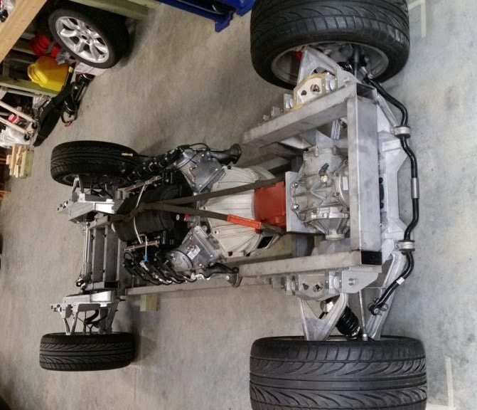
The next step involved discussion with the folks at Dobbertin Performance Innovations. With Mark's blessings, Bob purchased the front and rear suspension components that Dobbertin offers to customers wanting a Corvette C5 suspension attached to a narrower chassis like a Corvair. Once the suspension components arrived from Dobbertin, Bob started fabricating a custom chassis for the suspension components and the Corvair body under restoration back in Decatur, IL where Mark lives. Bob details his suspension work with the Dobbertin components on his website. Here's the link: https://reddragonautomotive.com/
Since this conversion is under construction as a race car, Bob elected to equip it with a power rack & pinion unit. He could have used an EPS (electric power steering) based on his experience, but decided that R&P works best in this application. In order to provide great traction, Mark wanted plenty of rubber on the road. Bob decided to use the standard 275-40R-18 Corvette wheels and tires. The Corvair wheel tubs were modified to accommodate this rather large footprint. In addition to the Corvette wheels, this Corvair racer is also equipped with the Corvette 4-wheel disc brakes. The brakes are power assisted.
This description summaries the work initially planned for this custom built Corvair race car. Bob plans to have Mark's car finished by the start of the Corvair convention. Mark Allen plans to debut his car at the autocross held during the CORSA convention in San Diego.
Listen To This Music -
The Adaptor
John Lanning has requested that all of you receive this information regarding the Saginaw 4spd gearbox to C5 Differential adapter.
My trip out to visit a few of you has been great and has provided a lot of insight as to what might be done in moving forward in this project.
I would like to thank Keith Waters and Tony Martin for all of their input in getting these components mated.
Many of us have our own ideas as to how to proceed and I believe that no one person has all the answers.
Camaraderie and discussion usually brings forward new ideas that are extremely useful. Here is my take on the adapter: Make it strong and simple to manufacture, try not to over design or reinvent.
The first step in building the adapter components was to fabricate the Saginaw Tailshaft bearing housing.
Keith Waters decided it was simpler to cut this housing from the Saginaw tailshaft,
You cannot miss getting it right by doing it this way, but seems like a lot of work.
Tony Martin added a machined lip to the hub to locate it's place on the Saginaw case. I elected to produce a simple hub, a tubular ring with two snap ring grooves, no lip,
The internal snap ring locates the bearing on the hub, the external snap ring locates the hub on the transmission case. When the 1" aluminum differential adapter plate is machined it will have a cutout bore to locate the hub insuring concentricity between the transmission mainshaft and pinion gear.
It also will have a .003" compression fit against the hub to add pressure to the snap ring keeping the hub from spinning. Now some may say that the hub should be pinned to stop any possible spinning of the hub, but keep this in mind. There is no press fit on the tailshaft bearing so the first place the bearing would spin would be in the bearing bore. This was a design decision made by GM and I know of no tailshaft housings being destroyed by bearings spinning in the bore.
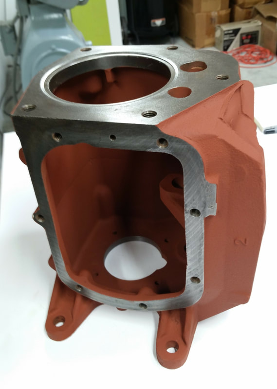
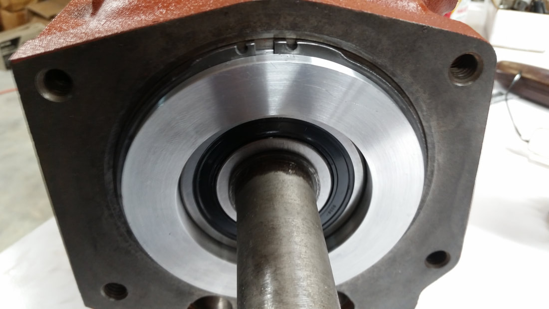
Here are a few photos of the hub and transmission case. I want to add that for some reason not known to me, the back end of the Saginaw case has been machined by GM for a snap ring. There is no snap ring used in the assembly of the case to the tailshaft in the GM Saginaw.
If anyone can answer this question, please advise. I decided to take advantage of this machined area.
Photo 1: This photo shows the machined area of the transmission case by GM for an external snap ring.
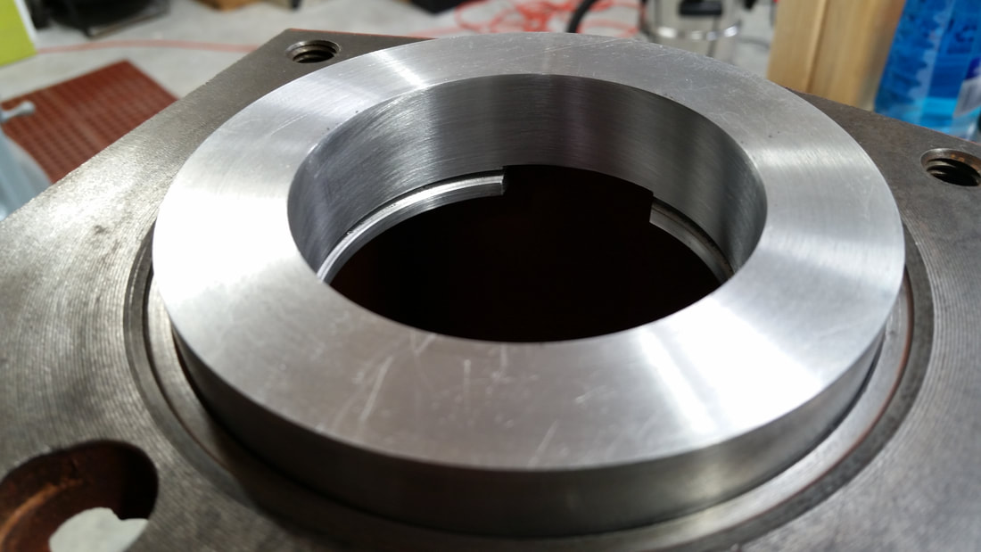
Photo 2: This photo shows the bearing housing with the internal snap ring groove for the bearing.
Photo 3: This photo shows the bearing hub in place with external snap ring and sealed bearing to keep the oil from migrating between the differential and transmission.
Sealed Bearing #: 6306 2RSNRJEM. External snap ring: McMaster Carr # 97633A516 * This snap ring must be ground to a maximum width of .235"
More to follow,
Bob.
Red Dragon Automotive.
www.reddragonautomotive.com
January, 2023 Update
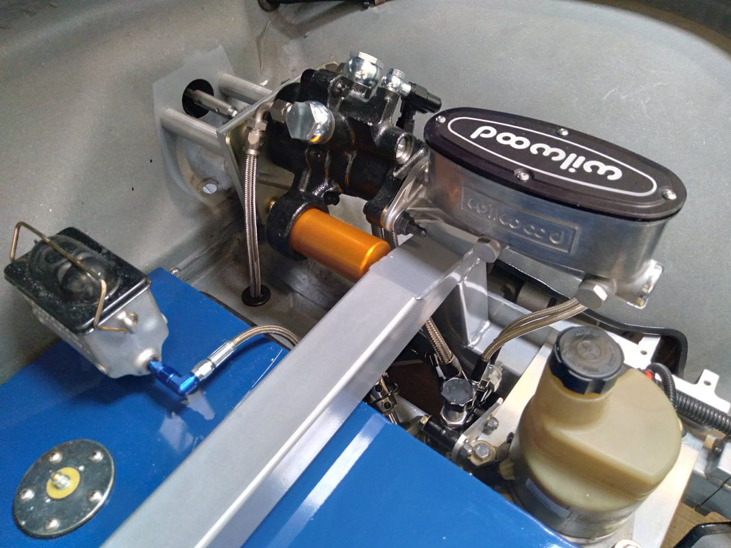
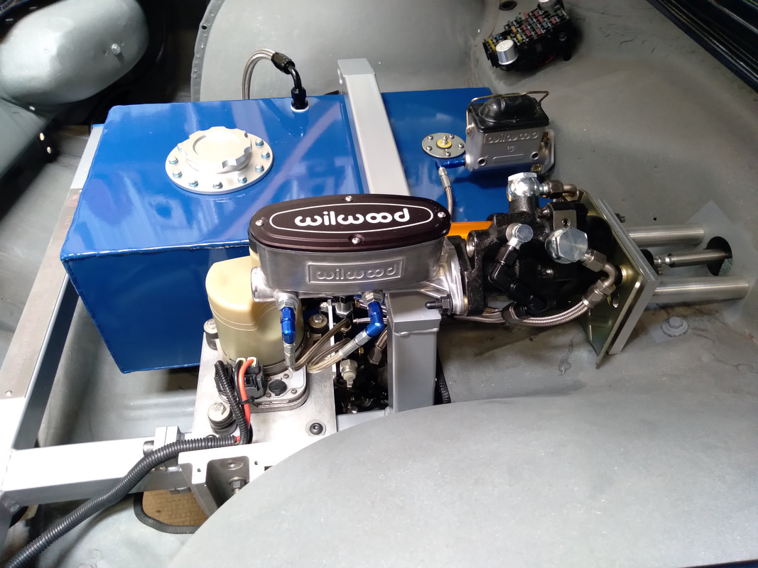
The HydroBoost is fully hydraulic and works off of the power steering pump. In Mark Allen's car, that pump is electric from a S70 Volvo and works in parallel with the power steering rack.
