Robert Snyder - Hilton, New York
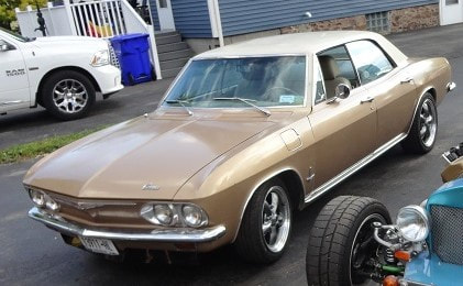
LS4 engine and 4T65eHD transmission & cooling system from an '06 Impala SS. Holley Terminator X engine and transmission controls. Mustang II power rack and pinion steering. Factory air conditioning using the compressor and condenser from Impala. All scratch fab, no kit.
The whole point of my build was to see if it could be done with a minimum of aftermarket parts and to produce a sleeper (other than the exhaust note) in a frumpy old 4-door. I confess that I already have an "attracts attention" car.
These are (most of) the major points of how I put the LS4 in my Corvair. If you have access to a 2006 - 2009 Impala, Monte Carlo or Grand Prix (either the one you are stripping or another one with an understanding owner) measure the dimension from the top of the strut to the A-arm pivot before you remove the parts - save this dimension for re-mounting the strut. This is not a show stopper, but it is one less problem to solve when the time comes.
The resources I used include welders (MIG, TIG & stick) and a small machine shop (lathe, mill and band saw) as well as the standard assortment of hand and power tools. The machine tools are not absolutely necessary but you will need to be a bit more creative without them.
If you want it to fit WITHOUT needing to flare the wheel wells and use the complete drop-out from the LS4, here are the "big pieces". Note (before you put a bunch of time and money in) that if you don't narrow the track, the upper mounting points for the struts go out to an almost inaccessible location under the roofline OR if you move them in enough to be reachable, the camber goes way out and must be dealt with. Your choice of wheels also becomes very limited. Your call...
1. '65-'69 bodies are 3" wider, and the rear wheel track will still need to be narrowed by 3". This leaves about 3/4" wiggle room. Using wheels with the proper offset (for the '06 Impala) up to a 235R45-18 tire will fit (245 if you trim the pinch weld). I don't believe that you can get away with a Gen1 body, it's 3" narrower.
2. The right hand "frame member" of the car will be removed as well as a portion of the frame in the area of the top of the strut towers on both sides. Be gentle with the car until the new subframe is installed.
3. You will need to build a subframe section around the engine which will weld into the car and form the strut towers.
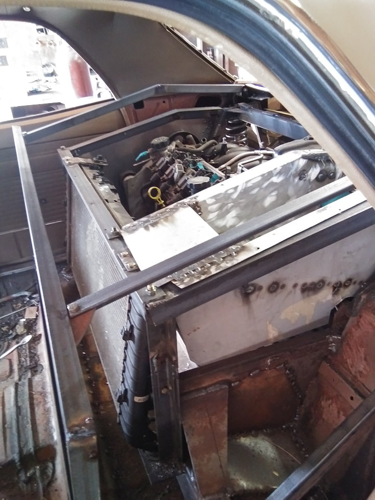
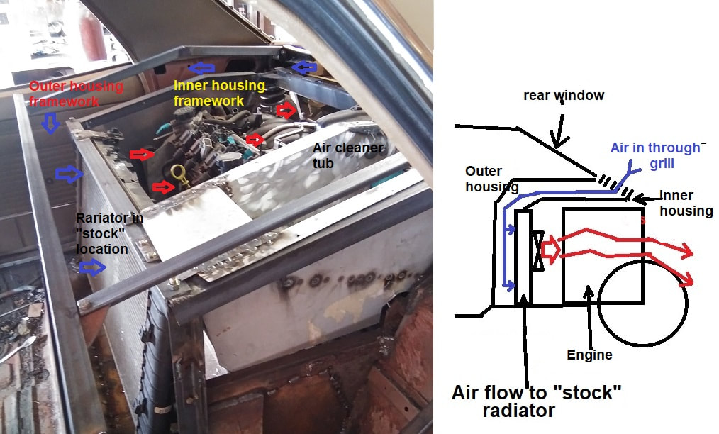
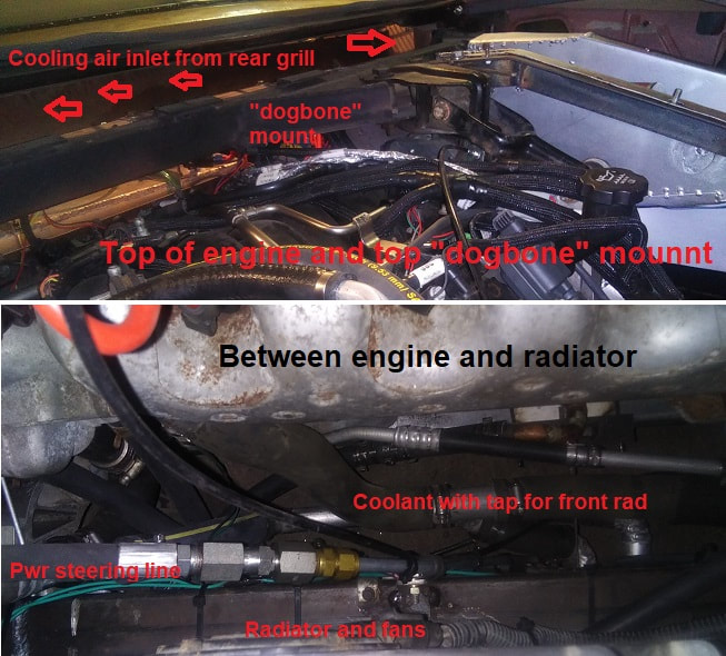
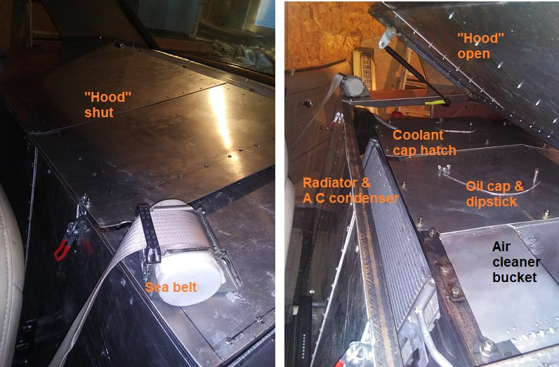
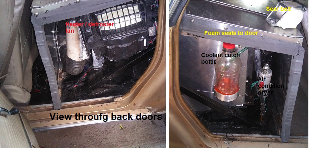
4. I kept the stock Impala radiator with fans in its stock location. An inner "dog house" surrounds the engine and air is drawn around it by the radiator fans - this air sweep under the outer housing keeps the heat from reaching the interior. A second radiator is mounted in front for added cooling when moving.
5. I used a 4-door for easier access to the area. After having done it once, a coupe could be done IF you are reasonably "fit and flexible". Note that if you do get a coupe, keeping the power steering and air conditioning compressor will be almost impossible to reach if you keep the radiator in the "stock" position. If you want to do a coupe, try to find an unsalvagable 4-door to do mock-up on if at all possible. Either way, removing the rear window is a must for the duration of the build. When I reinstalled mine, I used a "cutable foam" mounting so it is somewhat easier to remove if and when...
The wheel track needs to be narrowed a total of 3". This is done by re-drilling the mounting holes for the right hand A-arm inboard by 3/4" and narrowing the dropout cradle by 2 1/4". The right hand axle is 3" longer than the left. Get a second left hand shaft and swap the plunging joint (inner CV joint) from the RH shaft onto it. NOTE - when doing this swap the entire assembly (cup, rollers & spider) unless you are sure that both axles are virgin OEM parts since rebuilt axles shave the worn areas on the cup and spider and use different size rollers.
The alternator needs to be relocated. I made a new bracket as shown, the lower idler can be relocated on the new bracket to keep the original belt length and routing IF the power steering and air conditioning compressor are maintained. IF you delete one or both, you will need to reconfigure the whole drive and find the right length belt. The power steering reservoir will probably also need to be relocated if retained.
For engine control I used a Holley Terminator X Max which also controls the transmission. This requires an interface box to make the transmission look like a 4T80e to the Holley. I can provide one for the cost of parts or provide the schematics if you want to build your own. If you use the Holley or other aftermarket system you will need to delete the "AFM" on the engine and either change it over to a cable throttle or change the gas pedal to a DBW pedal (see the above note about the donor car). Note that the Holley can also control the "smart" alternator. I have a fairly good knowledge of both Terminator and Dominator installations and can help if that is the way you want to go. Another alternative is to modify the stock wiring harness (or have a new one made) and have the ECU(s) reprogrammed to delete "the rest of the car" so it will run as a stand alone unit.
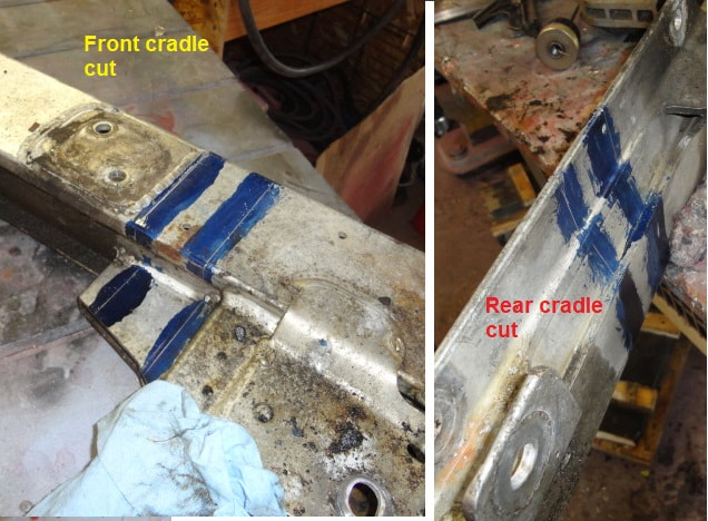
Some notes on the dropout cradle - shown are a couple of pics on where to cut and reweld it. I also put in backers on the rewelded areas and stitch bolted them for reinforcement. This leaves 2 of the 3 engine mounts untouched. The 3rd mount (right rear) needs to have a new pocket opened up and a new "floor plate" for it welded in to support it. The area under the front of the oil pan and the crank pulley also needs to be cut back slightly for clearance. The other modification that I did not do but would if I had a do-over is to cut the front mounting ears (arms?) off the cradle and add an extension with a new mounting crossmember the same width as the rest of the cradle. Fitting in the original ears requires more surgery on the car than would be otherwise needed. Drill new A-arm mounting holes 3/4" inboard on the right side - you may have to message the front of the A-arm slightly to prevent contact with the frame.
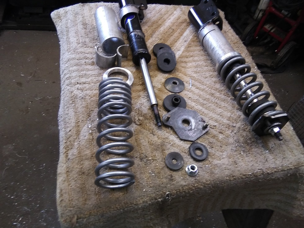
Now is a good time to talk about the struts. You will need them to mock up the strut towers. There isn't clearance for the original springs or top mounts. I uses 2 1/2" ID coil-over springs (400#, 9" QA1's since I had a set, 10" or 12" would work). Shave the spring cups off the struts and add a bottom spring mount (weld ONLY to the bottom bolt collar, NEVER to the shock body). Make up a top mount, insure that it allows for some deflection to avoid stressing the shaft. (I used cupped washers and rubber washers). Use the bumpers from inside the bellows on the original struts or make up new ones if they are unavailable. (a mud flap from a semi is a good source of durable rubber) Add spacers to the bottom for proper spring compression - 2" nominal (pipe size) aluminum conduit or 3" exhaust tube works well. If you can get a set of adjusters, great. Otherwise, give the length your best guess and redo if necessary once the car is full weight.
For the next steps, a hoist is nice, but you can get by with a chain fall to lift the back of the car and furniture dollies to move the subframe in and out.
In the following steps, you are going to be affecting the (anti)squat/weight transfer. I suggest reading several articles on weight transfer geometry of strut suspension. At this point you will need to determine the tilt (front to back) of the cradle which sets the axis of the lower element (A-arms). It can be adjusted subtly with shims under the cradle mounts after the final weld-in, but not a lot. Likewise, the position of the top mounts also affects the transfer, so bear that in mind when locating them.
I didn't take any pics of the subframe out of the car, but here are some of the details (more like pointers) on building the subframe (adapter) to be welded into the car. This is how I would do it next time. Open the area of the car that the engine will occupy - remember that you can always cut more. Leave all the frame rails intact for now. Remove the spring pockets. Put the lower control arms on the modified dropout, install the hub carriers on the control arms and brace them in position with the control arms horizontal (side-to-side), wheels pointing straight ahead (a long pipe through the hubs) and the strut mounts tilted slightly forward (where you want them when you are done).
Put the cradle WITHOUT THE ENGINE/TRANSMISSION under the car in the position (ride height and wheel well center) for your chosen tire diameter (recommend 25"-26") and body stance.
Build the perimeter of the new subframe to contact the frame rails (for eventual welding) on the body and add drop sections to meet the mounting pads on the dropout. USE ONLY TACK WELDS. Install enough temporary braces to keep its shape (rebar is cheap). Make sure that you make/leave enough alignment marks/tabs to put it back in the same place.
Remove the subframe and cradle together, remove the suspension mock-up and install the engine/transmission in it. This will require you to cut away some of the frame you just built. Build a new perimeter section around the "front" (crankshaft end) of the engine cutting away only what is necessary. Reenforce the tacks / add temporary bracing as you go. Allow for at least 1/2" (3/4" if possible) clearance around the "front" (crankshaft end) of the engine and retained accessories. Position the side member to clear the axle shaft swing at full suspension compression and allow access to the square hole on the belt tensioner arm.
Once the new perimeter is built and firmly TACKED together start reinstalling the engine/dropout cradle/subframe in the car, slicing and dicing as you go. When it is in, TACK it in place.
Reinstall the lower control arms and hub carriers, let them droop. Make up mating plates for the top strut mounts. Continue nibbling away the car to allow installation of the strut assemblies. The tops should be at the position you recorded earlier, or if that has been lost, about 2" below the rear window sill, as far outboard possible - this will put the camber within the range of a single camber adjusting bolt. Set the front-to-back position (angle of the strut) where you think you want it for weight transfer - as far back as possible works for me. Remember that you will probably need to access the fasteners after the rear window is reinstalled. Build the uprights (recommend an A-frame) from the perimeter subframe up to the mounts, and a cross member between them. This member should be as high as needed to clear the intake manifold and allow removal of the injector rack, but no higher since airflow from the cooling grill has to come forward over it. I suggest 1x2 or 1x3 tube mounted "flat". Add a mount for the "dogbone" upper motor mount that used to go to the radiator shell - IF you are going to reuse the stock dogbone, realize that any final shifting between the cradle and the subframe changes this dimension - tack it only for now.
Cut the tacks to the car, remove the assembly, separate it from the cradle/engine and do all the required welding EXCEPT for the dog bone mount. Reinstall the subframe in the car and weld it in. Fill in the open areas with sheet metal. Install the cradle / engine dropout assembly. When you reassemble everything, I recommend replacing the rubber mounts where the cradle meets the frame with solid slugs - do any final shifting/shimming then draw the cradle hard to the subframe. This will stiffen the whole thing more. When everything is assembled, finish weld the dog bone mount. (or, weld the mount in earlier and "adjust" the dog bone if needed). DO NOT just omit it all together unless you are using solid engine mounts - the stock rubber mounts will tear out from the engine torque.
New end eyes need to be formed on the sway bar if used. I annealed the clipped ends for a few inches and welded on new eyes made of 1/4" plate.
The rear brakes are the rear discs and cages from the Impala with calipers from a 2000 - 2005 Cadillac to get the parking brake. The cages need to be modified to fit the calipers and new brackets built. That's how I did it, you have endless choices... Just keep an eye on the disc thickness when mixing discs and calipers.
The last "issue" is locking the steering. I initially tried the obvious - "locking" the original steering linkage in it's original geometry. This produced a little wallow over bumps. Apparently when this happens in the front of a heavy car it's not a big deal but it's kind of spooky in the back. I made up a parallel link for the control arm and the behavior was notably better. Pics are shown of both versions.
When you have pretty much everything of significant weight in and the right wheels and tires on, look at the stance. If it isn't what you want, remove the struts and change the length of the spacer below the spring as required: 1" changes the ride about 1 1/4". BE SURE TO OBRERVE the caution about over-extending the axle below.
A couple of other notes... use the best struts you can get, I used Monroe police/taxi units. The 100,000 mile units from the donor are OK for set-up, but not what you want in the real world. When doing work involving the axles, DO NOT over-extend them or kink them at an extreme angle. The joint will pop apart in the boot and there is no way to get it back together without opening the boot (Yuck)... which means you will have to pull the shaft out of the transaxle... if the transaxle has the right amount of fluid, a big puddle of it will appear on the floor unless you jack up the car on its side about 2 feet BEFORE you pull the shaft. (don't ask me how I know this)... For cooling tubing, aluminum "rigid electrical conduit" is relatively cheap, can be bent to a reasonable degree without kinking, and TIG welds well. Note that it is measured in trade size, not actual OD... The low oil level switch in the pan is "backwards"-on when OK-you need a relay or an inverting circuit if you want to use it for the "oil" light. The alternator is controlled by the ECU - depending on what you use for engine controls, this might be of interest: https://ls1tech.com/forums/conversions-swaps/1912154-2-pin-2006-alternator-don-t-throw-away.html (read the first entry, ignore most of the following 100) If you use a Holley controller, I can help you do the control.
I did convert the steering to power rack and pinion and kept the air conditioning (it was a factory air car!) since I kept the pump and compressor on the motor, but that's one for another day that you may or may not want to get into anyway.
